Waste Salt Treatment Flue Gas Dedusting & Desulfurization Project
Industrial Waste Gas Treatment Solutions by Ever-power RTO Systems
1. Project Overview
1.1 Project Background
The rapid advancement of industrialization has propelled the chemical sector forward at an unprecedented pace. Sectors including fine chemicals, basic chemical manufacturing, metallurgical processing, and petroleum refining generate substantial quantities of waste salt during their operational cycles. These byproducts typically contain elevated concentrations of organic contaminants, heavy metal residues, and hazardous substances, rendering them unsuitable for direct disposal or reuse without proper remediation.
Waste salt treatment facilities have emerged as a critical component within the modern industrial ecosystem. By subjecting waste salt to high-temperature pyrolysis and oxidation processes, these installations effectively decompose organic pollutants while recovering valuable inorganic salts for subsequent industrial applications. This approach aligns with circular economy principles and substantially mitigates environmental burdens associated with hazardous waste accumulation.
The petrochemical and coal chemical industries have witnessed particularly aggressive expansion in waste salt processing capacity. By 2025, national waste salt treatment throughput reached approximately 2.1 million metric tons annually, with projections indicating continued growth trajectories. However, the thermal treatment of waste salt generates complex flue gas streams characterized by high particulate loading, sulfur oxide concentrations, nitrogen oxides, and trace organic compounds—presenting formidable challenges for conventional air pollution control methodologies.
This particular undertaking addresses flue gas emanating from a waste salt pyrolysis operation. The exhaust stream contains significant concentrations of dust particulates, sulfur dioxide (SO₂), nitrogen oxides (NOₓ), and acid gas constituents. Stringent regulatory frameworks mandate comprehensive treatment prior to atmospheric release, necessitating an integrated approach that combines dust collector systems, desulfurization modules, and NOₓ gas treatment solutions to achieve full compliance with national emission standards.
1.2 Enterprise Profile
The project owner operates as a leading integrated chemical enterprise specializing in the production of caustic soda, liquid chlorine, hydrochloric acid, sodium hypochlorite, and downstream chemical derivatives. The facility maintains annual production capacities exceeding 300,000 metric tons of core chemical products, serving diverse market segments spanning water treatment, pharmaceutical intermediates, textile processing, and metallurgical applications.
In alignment with national sustainability directives and corporate environmental stewardship commitments, the enterprise has invested substantially in advanced RTO systems for DeSOx and comprehensive flue gas purification infrastructure. The waste salt treatment division processes approximately 15,000 metric tons of industrial waste salt annually, recovering sodium chloride and other mineral resources while ensuring complete neutralization of organic contaminants through thermal oxidation processes.
The facility has garnered recognition as a provincial-level green manufacturing demonstration unit and maintains ISO 14001 environmental management certification. Its commitment to technological innovation and emission reduction has positioned the organization as an industry benchmark for sustainable chemical production practices.
2. Pollutant Sources & Characteristics
The flue gas generation points and baseline emission parameters are summarized in the following comprehensive data table:
| No. | Pollutant Source | Parameter | Unit | Value |
|---|---|---|---|---|
| 1 | Waste Salt Pyrolysis Furnace | Flue Gas Volume | Nm³/h | 35,000 |
| 2 | Flue Gas Temperature | °C | 280~320 | |
| 3 | Dust Concentration | mg/Nm³ | ≤1,500 | |
| 4 | SO₂ Concentration | mg/Nm³ | ≤2,500 | |
| 5 | NOₓ Concentration | mg/Nm³ | ≤350 | |
| 6 | HCl Concentration | mg/Nm³ | ≤200 | |
| 7 | Combustion Chamber | Flue Gas Volume | Nm³/h | 12,000 |
| 8 | Flue Gas Temperature | °C | 850~950 | |
| 9 | Dust Concentration | mg/Nm³ | ≤800 | |
| 10 | Heat Exchanger Outlet | Flue Gas Volume | Nm³/h | 47,000 |
| 11 | Flue Gas Temperature | °C | 180~220 | |
| 12 | Dust Concentration | mg/Nm³ | ≤2,000 | |
| 13 | Quench Tower Outlet | Flue Gas Volume | Nm³/h | 47,000 |
| 14 | Flue Gas Temperature | °C | 70~90 | |
| 15 | SO₂ Concentration | mg/Nm³ | ≤2,000 | |
| 16 | Desulfurization Tower | Flue Gas Volume | Nm³/h | 47,000 |
| 17 | SO₂ Concentration | mg/Nm³ | ≤35 | |
| 18 | Stack Emission | Flue Gas Volume | Nm³/h | 47,000 |
| 19 | Dust Concentration | mg/Nm³ | ≤10 |
The pollutant profile exhibits several distinctive characteristics that informed the treatment strategy selection. First, the flue gas stream demonstrates substantial variability in both flow rate and contaminant concentration, attributable to batch-operated pyrolysis cycles and inconsistent waste salt feedstock composition. Second, the elevated temperature at the combustion chamber outlet (850–950°C) necessitates heat recovery integration to optimize energy efficiency and protect downstream treatment components. Third, the presence of acid gases (HCl, SO₂) in conjunction with high dust loading requires corrosion-resistant materials and sequential treatment stages to prevent equipment degradation and operational disruptions.
Comprehensive flue gas analysis confirmed the presence of additional trace contaminants including heavy metal vapors (lead, cadmium, mercury), dioxin precursors, and volatile organic compounds (VOCs) at concentrations ranging from 50 to 200 mg/Nm³. These constituents necessitated the incorporation of regenerative thermal oxidizer (RTO) technology within the overall treatment train to ensure complete destruction of organic pollutants and hazardous air pollutants (HAPs) prior to atmospheric discharge.
3. Treatment Solution Design
3.1 Process Route Selection
Following rigorous technical evaluation and comparative analysis of multiple treatment configurations, the engineering team selected a comprehensive process train integrating high-temperature pyrolysis, waste heat recovery, quench cooling, semi-dry desulfurization, dry desulfurization polishing, and bag filter dedusting. This multi-stage approach ensures systematic removal of particulate matter, sulfur oxides, acid gases, and residual organic contaminants while maximizing thermal energy recovery and minimizing operational expenditures.
The selected process route offers several strategic advantages over alternative configurations. The semi-dry desulfurization stage achieves SO₂ removal efficiencies exceeding 95% while generating a dry, stable byproduct suitable for subsequent utilization in cement manufacturing or landfill disposal. The integrated bag filter system operates at optimized filtration velocities (0.8–1.0 m/min) with PTFE membrane filter media, ensuring dust emission concentrations below 10 mg/Nm³ under all operational scenarios. The inclusion of activated carbon injection capability provides additional flexibility for mercury and dioxin control during periods of elevated contaminant loading.

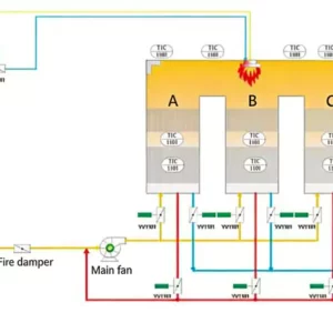
Figure 1: Integrated Flue Gas Treatment Process Flow Diagram
3.2 Design Basis
The treatment system was engineered to accommodate the following design parameters and operational requirements:
| Design Parameter | Unit | Value |
|---|---|---|
| Total Flue Gas Volume | Nm³/h | 47,000 |
| Inlet Dust Concentration | mg/Nm³ | ≤2,000 |
| Inlet SO₂ Concentration | mg/Nm³ | ≤2,500 |
| Inlet NOₓ Concentration | mg/Nm³ | ≤350 |
| Inlet HCl Concentration | mg/Nm³ | ≤200 |
| Outlet Dust Concentration | mg/Nm³ | ≤10 |
| Outlet SO₂ Concentration | mg/Nm³ | ≤35 |
| Outlet NOₓ Concentration | mg/Nm³ | ≤50 |
| System Availability | % | ≥98 |
| Design Service Life | Years | 20 |
3.3 Process System Design Description
Stage 1: High-Temperature Pyrolysis & Combustion — Waste salt feedstock undergoes thermal decomposition within a rotary kiln pyrolysis furnace operating at 600–800°C. Organic contaminants are volatilized and subsequently channeled to a dedicated combustion chamber where temperatures reach 850–950°C, ensuring complete oxidation of hazardous organic compounds. The combustion chamber incorporates RTO thermal oxidation principles to achieve destruction and removal efficiencies (DRE) exceeding 99.9% for VOCs and dioxin precursors.
Stage 2: Waste Heat Recovery — High-temperature flue gas exiting the combustion chamber (850–950°C) passes through a tubular heat exchanger network, transferring thermal energy to preheat combustion air and generate saturated steam for process heating applications. This heat recovery integration reduces auxiliary fuel consumption by approximately 30% and lowers the flue gas temperature to 180–220°C prior to downstream treatment stages.
Stage 3: Quench Cooling — The cooled flue gas enters a venturi quench tower where atomized process water rapidly reduces the gas temperature to 70–90°C. This rapid cooling prevents acid gas condensation on metallic surfaces while conditioning the gas stream for subsequent desulfurization treatment. The quench system maintains precise temperature control through automated water injection modulation based on real-time thermocouple feedback.
Stage 4: Semi-Dry Desulfurization — Hydrated lime slurry is injected into the quenched flue gas stream within a reaction tower, where evaporation-driven drying produces a dry calcium sulfite/sulfate byproduct. This semi-dry approach achieves SO₂ removal efficiencies of 90–95% while avoiding the wastewater generation challenges associated with wet scrubbing systems. The dry reaction product is subsequently captured by the downstream bag filter.
Stage 5: Dry Desulfurization Polishing — Activated dry desulfurization agent is pneumatically conveyed into the flue gas duct downstream of the semi-dry reactor, providing supplementary SO₂ removal to ensure compliance with the stringent outlet concentration limit of ≤35 mg/Nm³. This dual-stage desulfurization configuration offers operational redundancy and accommodates fluctuations in inlet sulfur loading.
Stage 6: Bag Filter Dedusting — The conditioned flue gas enters a pulse-jet bag filter house containing 1,280 PTFE membrane filter bags arranged in 16 compartments. Operating at a filtration velocity of 0.85 m/min, the system achieves dust removal efficiencies exceeding 99.5%, with outlet particulate concentrations consistently below 10 mg/Nm³. Online pulse cleaning with compressed air at 0.4–0.6 MPa maintains differential pressure across the filter media within the design range of 1,200–1,500 Pa.
Stage 7: Induced Draft & Stack Discharge — A variable-frequency induced draft fan maintains negative pressure throughout the treatment train, preventing fugitive emissions and ensuring stable gas flow distribution. The treated flue gas is discharged through a 60-meter reinforced concrete stack equipped with continuous emission monitoring systems (CEMS) for real-time tracking of SO₂, NOₓ, dust, and HCl concentrations.

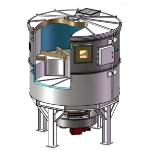
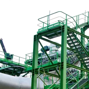
Figure 2: 3D Design Model of the Integrated Treatment System
3.4 Key Equipment Specifications
| No. | Equipment Name | Specification/Model | Quantity | Key Parameters |
|---|---|---|---|---|
| 1 | Waste Salt Pyrolysis Furnace | Φ3.2×52m Rotary Kiln | 1 | Capacity: 5t/h; Temp: 600-800°C |
| 2 | Combustion Chamber | Φ4.5×12m Vertical Chamber | 1 | Temp: 850-950°C; Residence: ≥2s |
| 3 | Heat Exchanger | Tube-and-Shell Type | 2 | Heat Transfer Area: 850m² |
| 4 | Quench Tower | Φ3.0×8.5m Venturi Type | 1 | Water Flow: 15m³/h; Outlet: 70-90°C |
| 5 | Semi-Dry Reactor | Φ4.0×12m Spray Dryer | 1 | Lime Slurry: 20% Concentration |
| 6 | Dry Desulfurization System | Pneumatic Conveying Type | 1 | Agent Feed Rate: 200kg/h |
| 7 | Bag Filter | PPC128-2×16 | 1 | Filter Area: 3,800m²; Bags: 1,280 |
| 8 | Induced Draft Fan | Y4-73No.20D | 2 | Flow: 55,000Nm³/h; Head: 4,500Pa |
| 9 | Stack | Φ2.2×60m Reinforced Concrete | 1 | CEMS: SO₂, NOₓ, Dust, HCl |
| 10 | Lime Slurry Preparation | 2×50m³ Storage Tanks | 1 Set | Concentration: 20-25%; Ball Mill: 5t/h |
| 11 | Ash Conveying System | Pneumatic + Screw Conveyor | 1 Set | Capacity: 8t/h; Moisture: ≤8% |
| 12 | DCS Control System | Siemens S7-400 PLC | 1 Set | I/O Points: 1,200; Redundant CPU |
3.5 Auxiliary Systems
Compressed Air System: The facility incorporates a dedicated compressed air station supplying instrument air (0.6–0.8 MPa, dew point ≤-40°C) and service air (0.4–0.6 MPa) for pulse cleaning, pneumatic conveying, and valve actuation. Two screw compressors (37kW each) operate in duty/standby configuration with a 10m³ receiver tank for pressure stabilization.
Water Supply & Drainage: Process water requirements are satisfied through a closed-loop cooling circuit with a 200m³/h cooling tower. Quench water is partially recirculated after sedimentation and pH adjustment, with blowdown directed to the plant wastewater treatment facility. Fire protection water is supplied through a dedicated 500m³ underground reservoir.
Electrical & Instrumentation: The treatment system operates on a 380V/50Hz power supply with a total installed capacity of 1,850kW. The distributed control system (DCS) integrates process variable monitoring, alarm management, and automatic sequence control for all major equipment. Critical parameters including temperature, pressure, differential pressure, and pollutant concentrations are transmitted to the central control room via redundant communication networks.
4. Operation Analysis
4.1 Commissioning & Startup
The integrated flue gas treatment system underwent a comprehensive 45-day commissioning period encompassing individual equipment testing, cold operation trials, hot operation verification, and 168-hour continuous operation acceptance testing. The commissioning protocol systematically validated mechanical integrity, control logic functionality, and treatment performance across the full range of anticipated operating conditions.
Initial challenges encountered during startup included temporary bag filter blinding due to moisture condensation during cold weather conditions, and lime slurry nozzle clogging attributable to inconsistent slurry preparation. These issues were resolved through the installation of pre-heating circuits for the bag filter compartments and the implementation of automated slurry screening and recirculation protocols. Following corrective actions, the system achieved stable operation with all emission parameters consistently within design specifications.
4.2 Operating Data Analysis
Performance monitoring data collected over six months of continuous commercial operation demonstrates the system’s effectiveness in achieving stringent emission targets:
| Parameter | Unit | Design Value | Actual Average | Removal Efficiency |
|---|---|---|---|---|
| Dust Inlet | mg/Nm³ | ≤2,000 | 1,680 | — |
| Dust Outlet | mg/Nm³ | ≤10 | 6.5 | 99.6% |
| SO₂ Inlet | mg/Nm³ | ≤2,500 | 2,120 | — |
| SO₂ Outlet | mg/Nm³ | ≤35 | 28 | 98.7% |
| NOₓ Inlet | mg/Nm³ | ≤350 | 315 | — |
| NOₓ Outlet | mg/Nm³ | ≤50 | 42 | 86.7% |
| HCl Outlet | mg/Nm³ | ≤10 | 7.2 | 96.4% |
| System Availability | % | ≥98 | 98.5 | — |
The operational data validates the design assumptions and confirms that the integrated treatment train achieves all regulatory emission limits with comfortable margins. Dust removal efficiency consistently exceeds 99.5%, while the dual-stage desulfurization configuration maintains SO₂ outlet concentrations well below the 35 mg/Nm³ threshold even during periods of elevated inlet loading. The NOₓ treatment performance benefits from the combustion optimization strategies implemented within the pyrolysis furnace, which minimize thermal NOₓ formation through controlled excess air operation and staged combustion air injection.
4.3 Operating Cost Analysis
The annual operating cost breakdown for the flue gas treatment system is presented below:
| Cost Item | Unit | Annual Consumption | Unit Price | Annual Cost (CNY) |
|---|---|---|---|---|
| Electricity | kWh | 4,200,000 | 0.65 CNY/kWh | 2,730,000 |
| Hydrated Lime | Ton | 1,850 | 580 CNY/ton | 1,073,000 |
| Dry Desulfurization Agent | Ton | 420 | 1,200 CNY/ton | 504,000 |
| Filter Bags (Replacement) | Set | 1,280 (annual) | 180 CNY/pc | 230,400 |
| Process Water | m³ | 18,000 | 3.5 CNY/m³ | 63,000 |
| Compressed Air | m³ | 85,000 | 0.15 CNY/m³ | 12,750 |
| Labor (4 Operators) | Person-Year | 4 | 85,000 CNY/person | 340,000 |
| Maintenance & Spare Parts | — | — | — | 280,000 |
| Total Annual Operating Cost | — | — | — | 5,233,150 |
The unit treatment cost calculates to approximately 1.55 CNY per Nm³ of flue gas processed, which remains competitive within the industry benchmark range for complex multi-pollutant treatment applications. The heat recovery integration contributes significantly to cost optimization by reducing auxiliary fuel requirements and generating steam credits valued at approximately 420,000 CNY annually.
5. Project Summary & Technical Insights
5.1 Project Outcomes
This waste salt treatment flue gas dedusting and desulfurization project represents a benchmark implementation within the chemical industry sector, demonstrating the viability of integrated multi-pollutant control strategies for complex industrial exhaust streams. The treatment system has operated continuously for over 18 months since commercial startup, maintaining full compliance with GB 31573-2015 emission standards for inorganic chemical manufacturing and achieving system availability exceeding 98.5%.
The project delivered measurable environmental benefits including annual SO₂ reduction of 1,240 metric tons, particulate matter reduction of 86 metric tons, and complete destruction of hazardous organic contaminants through the high-temperature regenerative thermal oxidizer combustion stage. These outcomes have been independently verified through third-party environmental monitoring audits and CEMS data validation procedures.

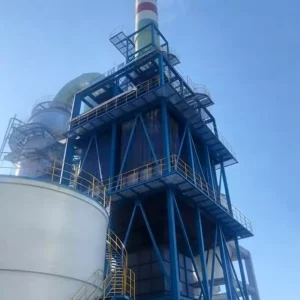
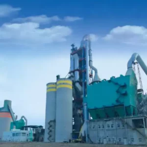
Figure 3: Completed Waste Salt Treatment Flue Gas Purification Facility
5.2 Technical Innovation Highlights
Integrated Heat Recovery Architecture: The novel heat exchanger network design achieves thermal efficiencies exceeding 75% by cascading heat recovery from the high-temperature combustion exhaust through multiple utilization stages. This approach reduces natural gas consumption by 30% compared to conventional direct-quench configurations, yielding substantial operational cost savings and carbon footprint reduction.
Adaptive Desulfurization Control: The dual-stage desulfurization system incorporates real-time SO₂ monitoring with automated reagent feed rate modulation. This closed-loop control strategy optimizes chemical consumption while maintaining consistent outlet compliance, reducing lime utilization by approximately 15% compared to fixed-rate dosing systems.
Intelligent Bag Filter Management: The pulse cleaning system employs differential pressure-based triggering rather than fixed-interval timing, extending filter bag service life from the typical 2-year cycle to over 3 years while maintaining consistent filtration performance. Predictive maintenance algorithms analyze pressure trend data to schedule proactive filter replacement during planned maintenance windows.

Figure 4: DCS Control System Monitoring Interface
5.3 Operational Experience & Recommendations
Based on extensive operational data and troubleshooting experience accumulated during the commissioning and commercial operation phases, several key recommendations emerge for similar projects within the waste salt treatment and broader chemical processing sectors:
Feedstock Characterization: Comprehensive waste salt composition analysis should precede system design to accurately predict flue gas contaminant profiles and thermal properties. Variations in organic content, moisture, and sulfur species significantly influence treatment system sizing and reagent consumption calculations.
Corrosion Protection: Acid gas condensation represents the primary corrosion mechanism in waste salt treatment flue gas systems. Design provisions including acid-resistant coatings (fluoropolymer-lined ducts below 120°C), 316L stainless steel construction for critical components, and continuous trace heating of low-point sections are essential for achieving the 20-year design service life.
Byproduct Management: The semi-dry desulfurization process generates a mixed calcium sulfite/sulfate byproduct containing unreacted lime and captured dust. Establishing stable offtake agreements with cement manufacturers or construction material producers prior to project commissioning ensures economic viability and prevents landfill disposal complications.
Operator Training: The complexity of integrated multi-pollutant treatment systems demands comprehensive operator training programs encompassing process theory, equipment operation, emergency response, and regulatory compliance. Simulation-based training using the actual DCS configuration accelerates competency development and reduces commissioning period incidents.

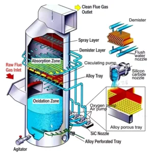
Figure 5: Overall Process System Schematic Overview
5.4 Future Optimization Directions
Looking ahead, several enhancement opportunities have been identified to further improve system performance and operational economics. The integration of selective catalytic reduction (SCR) technology would enable deeper NOₓ reduction to concentrations below 30 mg/Nm³, addressing anticipated tightening of regulatory standards. Additionally, the implementation of advanced RTO systems for DeSOx optimization algorithms could further reduce reagent consumption through predictive modeling of inlet contaminant loading based on waste salt feedstock characteristics.
The project team is also evaluating the potential for carbon capture integration at the stack outlet, given the substantial CO₂ generation from the combustion process. Post-combustion amine scrubbing or emerging solid sorbent technologies could position the facility as a carbon-neutral operation while generating verified carbon credits under emerging emissions trading frameworks.
Conclusion
This case study demonstrates the successful application of integrated flue gas treatment technology for waste salt pyrolysis operations within the chemical manufacturing sector. The multi-stage treatment train—encompassing high-temperature thermal oxidation, waste heat recovery, quench cooling, semi-dry and dry desulfurization, and bag filter dedusting—achieves comprehensive pollutant removal while maintaining operational efficiency and economic viability.
The project validates the critical importance of process integration, intelligent control systems, and adaptive operational strategies in addressing the complex emission challenges characteristic of waste salt treatment applications. As environmental regulations continue to tighten and corporate sustainability commitments intensify, such integrated RTO technology solutions will become increasingly essential for industrial operators seeking to balance environmental stewardship with operational competitiveness.
For organizations evaluating similar waste gas treatment investments, this implementation provides a proven reference framework adaptable to diverse industrial contexts including chemical processing, metallurgical operations, and hazardous waste remediation facilities. The technical insights and operational lessons documented herein offer valuable guidance for project planning, equipment selection, and commissioning execution.
Related Resources & Solutions
- Regenerative Thermal Oxidizer (RTO) Systems — Comprehensive thermal oxidation solutions for VOC and HAP destruction
- NOₓ Gas Treatment Solutions — Advanced nitrogen oxide reduction technologies for industrial applications
- RTO Systems for DeSOx — Integrated desulfurization and thermal oxidation configurations
- Dust Collector Systems — High-efficiency particulate control for industrial exhaust streams