Steel Industry Dedusting & Desulfurization Project
Integrated Flue Gas Treatment for Steel Manufacturing by Ever-power RTO Systems
1. Project Overview
1.1 Industry Background
The steel manufacturing sector generates substantial quantities of dust and particulate matter throughout its operational cycle, with byproduct dust and ash arising from multiple production stages including electric arc furnaces, blast furnaces, sintering operations, and smelting processes. In particular, the sintering and refining phases produce significant volumes of dust-laden exhaust that, if left untreated, pose serious environmental and public health risks. The steelmaking stage represents one of the most intensive sources of particulate emissions, with electric furnace operations generating dust at rates of 12 to 20 kilograms per metric ton of steel produced, and iron oxide content in the dust stream frequently exceeding 40% by mass.
Beyond the steel sector itself, related heavy industries including crane manufacturing, electrical equipment production, and shipbuilding generate comparable dust emissions that compound regional air quality challenges. Effective dust management within steel plants therefore demands not merely collection and containment, but also resource recovery and circular utilization strategies that transform waste streams into valuable secondary raw materials. The annual discharge of dust ash from steel operations has reached enormous scales, creating urgent imperatives for comprehensive emission control infrastructure.
This project addresses the rotary kiln combustion exhaust from a steel production facility, targeting the removal of sulfur dioxide, particulate matter, and acidic gas constituents to achieve full compliance with the stringent Steel Industry Air Pollutant Ultra-Low Emission Standard (DB13/2169-2018). The facility utilizes natural gas as its primary fuel, and the treatment system has been engineered to reduce outlet SO2 concentrations below 20 mg/Nm3, particulate matter below 5 mg/Nm3, and eliminate visible white plume trailing phenomena through integrated regenerative thermal oxidizer (RTO) and flue gas purification technologies.
1.2 Enterprise Profile
The project owner operates as a prominent steel enterprise headquartered in Tangshan, Hebei Province, established in 2004. The company maintains domestic-leading structural steel and high-speed wire rod production lines, having developed a vertically integrated steel marketing industrial chain encompassing steelmaking, rolling, processing, warehousing, and logistics operations. Its product portfolio serves markets across China and exports to international destinations worldwide, with a customer base exceeding 6,000 domestic and foreign clients.
The enterprise adheres to a development philosophy centered on green, clean, and low-carbon manufacturing principles, with comprehensive energy conservation and environmental protection facilities installed throughout all production stages. The facility employs reverse osmosis technology for wastewater treatment, achieving treated water quality surpassing drinking water standards and realizing true zero-discharge wastewater management. The company has also successfully developed and implemented waste heat recovery systems utilizing blast furnace slag water and flue gas heat for wood drying applications, demonstrating industry-leading innovation in energy cascade utilization.
Committed to achieving the Steel Industry Air Pollutant Ultra-Low Emission Standard (DB13/2169-2018), the enterprise has invested in upgrading its rotary kiln combustion system and installing advanced flue gas treatment infrastructure including acid gas scrubbing, wet desulfurization, wet electrostatic precipitation, and flue gas plume suppression systems. These environmental technologies have substantially elevated the facility’s pollution control capabilities while contributing positively to regional air quality improvement.
2. Pollutant Sources & Environmental Data Analysis
The environmental treatment data analysis for this steel industry project is comprehensively summarized in the following table:
| Nie. | Category | Item | Steel Industry | Unit | Remarks |
|---|---|---|---|---|---|
| 1 | Pollution Source | Kiln Type | Rotary Kiln | — | — |
| 2 | Fuel (Natural Gas) Consumption | 5,500 | m3/h | — | |
| 3 | Standard Flue Gas Volume | 56,890 | Nm3/h | — | |
| 4 | Flue Gas Temperature | 150~160 | °C | — | |
| 5 | Operating Flue Gas Volume | 90,213 | Nm3/h | — | |
| 6 | Actual Oxygen Content | 15 | % | — | |
| 7 | Baseline Oxygen Content | 12 | % | — | |
| 8 | Fan Power | 200 | kW | — | |
| 9 | Duct Parameters | Wind Pressure | 5,000 | Pa | — |
| 10 | Duct Diameter | φ1,820 | mm | — | |
| 11 | Initial Concentration Parameters | Nitrogen Oxides | 50 | mg/Nm3 | — |
| 12 | Sulfur Dioxide | 2,800 | mg/Nm3 | — | |
| 13 | Particulate Matter | 100 | mg/Nm3 | — | |
| 14 | Carbon Monoxide | 4,000 | mg/Nm3 | — | |
| 15 | Hydrogen Fluoride | 15 | mg/Nm3 | — | |
| 16 | Hydrogen Chloride | 50 | mg/Nm3 | — | |
| 17 | Temperature Points | Before Dust Removal | 60 | °C | — |
| 18 | Before Desulfurization | 150 | °C | — | |
| 19 | Plume Suppression Inlet | 55 | °C | — | |
| 20 | Humidity | — | — | — | |
| 21 | Corrosivity | Other Corrosive Substances & Concentration | 30 | mg/Nm3 | NaCl |
| 22 | Treatment Process | Desulfurization | Limestone-Gypsum Method | — | — |
| 23 | Dust Removal | Wet Electrostatic Precipitator | — | — | |
| 24 | Deacidification | Wet Deacidification | — | — | |
| 25 | Plume Suppression | MGGH Heat Exchange | — | — | — |
| 26 | Discharge Standard Requirements | Emission Standard | DB13/2169-2018 | — | Steel Industry Ultra-Low Emission Standard |
| 27 | Nitrogen Oxides | 50 | mg/Nm3 | — | |
| 28 | Sulfur Dioxide | 20 | mg/Nm3 | — | |
| 29 | Particulate Matter | 5 | mg/Nm3 | — | |
| 30 | Carbon Monoxide | 100 | mg/Nm3 | — | |
| 31 | Hydrogen Fluoride | 5 | mg/Nm3 | — | |
| 32 | Hydrogen Chloride | 20 | mg/Nm3 | — | — |
| 33 | Plume Suppression | No Visible White Plume | — | — | — |
| 34 | Treatment Efficiency | Desulfurization Efficiency | 99.28 | % | — |
| 35 | Denitrification Efficiency | — | % | — | |
| 36 | Dust Removal Efficiency | 75 | % | — | |
| 37 | Carbon Monoxide Removal Efficiency | 97.50 | % | — | |
| 38 | Hydrogen Fluoride Removal Efficiency | 66.67 | % | — | |
| 39 | Hydrogen Chloride Removal Efficiency | 60.00 | % | — | — |
The pollutant profile for this steel industry application presents several distinctive characteristics that informed the treatment strategy. The flue gas stream exhibits exceptionally high sulfur dioxide concentrations (2,800 mg/Nm3) attributable to sulfur-containing raw materials and fuel combustion within the rotary kiln. Particulate matter levels (100 mg/Nm3) comprise primarily iron oxide fines, metallic dusts, and combustion ash. Acid gas constituents including hydrogen fluoride (15 mg/Nm3) and hydrogen chloride (50 mg/Nm3) originate from chlorides and fluorides present in the ore feedstock and fuel. The elevated carbon monoxide concentration (4,000 mg/Nm3) reflects incomplete combustion within the rotary kiln system. The presence of sodium chloride at 30 mg/Nm3 introduces additional corrosion risks that must be addressed through appropriate materials selection.
The DB13/2169-2018 ultra-low emission standard mandates stringent outlet limits: SO2 ≤20 mg/Nm3, particulate matter ≤5 mg/Nm3, NOx ≤50 mg/Nm3, CO ≤100 mg/Nm3, HF ≤5 mg/Nm3, and HCl ≤20 mg/Nm3. Achieving these targets requires treatment efficiencies exceeding 99% for sulfur dioxide and 95% for particulate matter, necessitating a multi-stage integrated approach combining RTO systems for DeSOx with advanced particulate capture technologies.
3. Treatment Solution Design
3.1 Process Route Selection
The enterprise has established an integrated environmental management and control platform incorporating air quality micro-stations and total suspended particulate concentration monitoring instruments to achieve comprehensive real-time monitoring, early warning, and intelligent coordinated control of emissions. These measures have substantially elevated the facility’s environmental governance capabilities and enabled successful achievement of ultra-low emission targets.
The flue gas treatment process train operates as follows: After passing through the bag filter dust removal system, the 160°C flue gas is directed into an MGGH (Media Gas-Gas Heat Exchanger) cooler, reducing the gas temperature to 115°C while simultaneously heating the thermal medium water from 89°C to 109°C. The cooled flue gas then enters a scrubbing tower equipped with three spray levels for effective removal of HCl and other acidic gas constituents. Following acid gas neutralization, the gas stream proceeds to the desulfurization tower for sulfur dioxide removal, utilizing four spray levels to ensure adequate SO2 absorption. The desulfurized gas then passes through a wet electrostatic precipitator for final particulate polishing, achieving full emission compliance while eliminating visible white plume trailing phenomena. This integrated regenerative thermal oxidizer (RTO) approach exemplifies best practices for steel industry emission control.

Figure 1: Integrated Flue Gas Treatment Process Flow Diagram for Steel Manufacturing
3.2 Design Model
The 3D design models illustrate the spatial configuration of major treatment equipment, ductwork routing, and auxiliary system integration. The layout optimizes equipment spacing for maintenance access while minimizing pressure losses through streamlined duct configurations. The induced draft fans are positioned to protect rotating equipment from corrosive gas exposure, while the stack is located at the highest elevation point to ensure adequate natural draft and dispersion characteristics.

Figure 2: 3D Design Model 1 of the Integrated Steel Industry Flue Gas Purification Facility

Figure 3: 3D Design Model 2 of the Integrated Steel Industry Flue Gas Purification Facility
3.3 Process Requirements & Design Considerations
The flue gas plume suppression technology employed in this project represents a mature and reliable approach, with all selected equipment, accessory materials, manufacturing processes, and inspection requirements meeting or exceeding relevant national standards. The system is designed to maintain consistent plume suppression efficiency across the full range of anticipated operating variations in dust content, sulfur dioxide concentration, and acid gas levels.
The MGGH heat exchanger system incorporates specialized design provisions to prevent tube wear, leakage, and corrosion issues. Appropriate stainless steel tubing selection, optimized flue gas velocity profiles, and refined duct structural configurations collectively reduce corrosion rates and extend equipment service life, enhancing the universal applicability of MGGH technology across diverse industrial contexts.
Engineering site layout planning ensures adequate space allocation for all system equipment. The treatment process generates no secondary pollution, and system reagents are sourced from stable, reliable supply chains. All procured equipment represents premium domestic and international brands. The process design emphasizes energy and water conservation through the application of energy-efficient technologies and equipment, reducing both capital investment and operational expenditures.
Ambient noise levels surrounding the treatment facility comply with Class II standards under the Industrial Enterprise Boundary Environmental Noise Emission Standard (GB 12348-2008), with equipment operating noise maintained below 85 dB at a 1-meter measurement distance. The modular design concept accommodates evolving environmental requirements across different operational periods. The advanced process technology simultaneously eliminates visual pollution and reduces atmospheric pollutant emissions, achieving ultra-low discharge levels that satisfy both current and anticipated regulatory frameworks over the next three to five years.
3.4 Design Calculation Summary
The design calculations for this project are summarized in the following comprehensive tables:
3.4.1 Flue Gas Cooling Heat Exchanger
| Nie. | Item | Unit | Value |
|---|---|---|---|
| 1 | Flue Gas Volume | m3/h | 52,320 |
| 2 | Heat Exchange Area | m2 | 400 |
| 3 | Equipment Pressure Drop | Pa | 430 |
| 4 | Hot Side Inlet Temperature | °C | 160 |
| 5 | Hot Side Outlet Temperature | °C | 115 |
| 6 | Thermal Medium Water Inlet Temperature | °C | 89 |
| 7 | Thermal Medium Water Outlet Temperature | °C | 109 |
| 8 | Equipment Dimensions | mm×mm×mm | 3,000×2,120×3,524 |
3.4.2 Scrubbing Tower
| Nie. | Item | Unit | Value |
|---|---|---|---|
| 1 | Flue Gas Volume | m3/h | 80,841 |
| 2 | Inlet Flue Gas Temperature | °C | 115 |
| 3 | Outlet Flue Gas Temperature | °C | 65 |
| 4 | Wind Speed | m/s | 2.4 |
| 5 | Scrubbing Tower Diameter | m | φ3.5 |
| 6 | Spray Layers | Layer | 2 |
| 7 | Single Pump Flow Rate | m3/h | 80 |
| 8 | Scrubbing Tower Height | m | 23 |
3.4.3 Desulfurization Tower
| Nie. | Item | Unit | Value |
|---|---|---|---|
| 1 | Flue Gas Volume | m3/h | 70,500 |
| 2 | Flue Gas Temperature | °C | 65 |
| 3 | SO2 Inlet Concentration | mg/Nm3 | 2,800 |
| 4 | SO2 Outlet Concentration | mg/Nm3 | 20 |
| 5 | Calcium-to-Sulfur Ratio | — | 1.05 |
| 6 | Wind Speed | m/s | <3.2 |
| 7 | Tower Inner Diameter | m | φ2.8 |
| 8 | Liquid-to-Gas Ratio | — | 22.8 |
| 9 | Spray Layers | Layer | 4 |
| 10 | Single Pump Flow Rate | m3/h | 325 |
| 11 | Slurry Retention Time | h | 3.5 |
| 12 | Limestone Operating Consumption | kg/h | 275 |
| 13 | Gypsum Production | kg/h | 395 |
| 14 | Gypsum Moisture Content | % | 12~15 |
| 15 | Demister | — | 2-Layer Ridge + 1-Layer Tube Type |
| 16 | Limestone Silo Volume | m3 | 30 |
| 17 | Service Life | d | 4.5 |
3.4.4 Wet Electrostatic Precipitator
| Nie. | Item | Unit | Value |
|---|---|---|---|
| 1 | Flue Gas Volume | m3/h | 70,500 |
| 2 | Flue Gas Temperature | °C | 65 |
| 3 | Precipitator Design Velocity | m/s | 1.4 |
| 4 | Anode Tube Effective Cross-Sectional Area | m2 | 14.16 |
| 5 | Dust Collection Area | m2 | 943.5 |
| 6 | Outlet Dust Emission Concentration | mg/Nm3 | 5 |
| 7 | Body Resistance | Pa | 300 |
| 8 | Anode Tube Specifications | mm×mm | Inscribed Circle φ360×6,000 |
| 9 | Anode Tube / Cathode Wire Total Quantity | Piece | 128 |
| 10 | Cathode Wire Material | — | 2205 |
| 11 | Power Supply Type | — | High Frequency Power Supply |
| 12 | Power Supply Parameters | — | 72 kV / 800 mA |
| 13 | Specific Collection Area | m2/(m3·s) | 37 |
3.4.5 Flue Gas Reheating Heat Exchanger
| Nie. | Item | Unit | Value |
|---|---|---|---|
| 1 | Flue Gas Volume | m3/h | 53,366.4 |
| 2 | Heat Exchange Area | m2 | 812 |
| 3 | Equipment Pressure Drop | Pa | 370 |
| 4 | Flue Gas Inlet Temperature | °C | 50 |
| 5 | Flue Gas Outlet Temperature | °C | 90 |
| 6 | Thermal Medium Water Inlet Temperature | °C | 108 |
| 7 | Thermal Medium Water Outlet Temperature | °C | 90 |
| 8 | Equipment Dimensions | mm×mm×mm | 3,000×2,120×4,004 |
3.4.6 Induced Draft Fan
| Nie. | Item | Unit | Value |
|---|---|---|---|
| 1 | Single Unit Flow Rate | m3/h | 90,000 |
| 2 | Wind Pressure | Pa | 6,000 |
| 3 | Prevádzková teplota | °C | 150 |
| 4 | Single Unit Power | kW | 220 |
4. Operation Analysis
4.1 Energy Consumption Analysis
The energy consumption analysis for this project is detailed in the following comprehensive equipment power summary table:
| Nie. | Názov zariadenia | Single Unit Rated Power (kW) | Total Units | Total Power (kW) | Actual Working Units | Actual Working Power (kW) | Operating Status |
|---|---|---|---|---|---|---|---|
| 1 | Main Induced Draft Fan | 220 | 1 | 220 | 1 | 220 | — |
| 2 | Desulfurization Tower Circulation Pump | 55 | 4 | 220 | 3 | 165 | Full Operation Considered |
| 3 | Slurry Transfer Pump | 7.5 | 2 | 15 | 1 | 7.5 | 1 Standby, 1 Operation (Intermittent) |
| 4 | Oxidation Blower | 22 | 3 | 66 | 2 | 44 | 2 in Use, 1 Standby |
| 5 | Desulfurization Tower Side Agitator | 4 | 3 | 12 | 3 | 12 | Full Operation |
| 6 | Fluidization Fan Heater | 5.5 | 1 | 5.5 | 1 | 5.5 | Full Operation Considered (Actual Intermittent) |
| 7 | Star-Type Feeder | 0.55 | 1 | 0.55 | 1 | 0.55 | Full Operation Considered (Actual Intermittent) |
| 8 | Rapping Motor | 0.25 | 1 | 1.1 | 1 | 0.25 | Full Operation Considered (Actual Intermittent) |
| 9 | Screw Conveyor | 2.2 | 1 | 2.2 | 1 | 2.2 | Full Operation Considered (Actual Intermittent) |
| 10 | Limestone Slurry Tank Agitator | 4 | 1 | 4 | 1 | 4 | Full Operation |
| 11 | Slurry Pump | 4 | 2 | 8 | 1 | 4 | 1 Standby, 1 Operation (Intermittent) |
| 12 | Gypsum Discharge Pump | 22 | 2 | 44 | 1 | 22 | 1 Standby, 1 Operation (Intermittent) |
| 13 | Vacuum Belt Filter | 37 | 1 | 37 | 1 | 37 | Full Operation Considered (Actual Intermittent 2h) |
| 14 | Filtrate Agitator | 4 | 1 | 4 | 1 | 4 | Full Operation |
| 15 | Filtrate Transfer Pump | 3 | 2 | 6 | 1 | 3 | 1 Standby, 1 Operation (Intermittent) |
| 16 | Emergency Discharge Pump | 15 | 1 | 15 | 1 | 15 | 1 Standby, 1 Operation (Intermittent) |
| 17 | Emergency Agitator | 7.5 | 1 | 7.5 | 1 | 7.5 | Intermittent Operation |
| 18 | Tower Area Discharge Pump | 2.2 | 2 | 4.4 | 1 | 2.2 | 1 Standby, 1 Operation (Intermittent) |
| 19 | Tower Area Agitator | 4 | 1 | 4 | 1 | 4 | Full Operation |
| 20 | Process Water Pump | 5.5 | 2 | 11 | 1 | 5.5 | 1 Standby, 1 Operation |
| 21 | Flushing Water Pump | 15 | 2 | 30 | 1 | 15 | 1 Standby, 1 Operation (Intermittent) |
| 22 | Heat Exchanger Water Pump | 22 | 2 | 44 | 1 | 22 | 1 Standby, 1 Operation |
| 23 | Wet Electrostatic Precipitator | 57.6 | 1 | 57.6 | 1 | 57.6 | Full Operation |
| 24 | Shielded Fan | 11 | 2 | 22 | 2 | 22 | Full Operation |
| 25 | Conduction Box Electric Heater | 2 | 4 | 8 | 4 | 8 | Full Operation |
| 26 | Shielded Box Electric Heater | 0.3 | 4 | 1.2 | 4 | 1.2 | Full Operation |
| — | Total | — | — | 850.05 | — | 691 | — |
The maximum operating load for the main equipment reaches 691 kW, with continuous 24-hour daily operation. At an average electricity tariff of 0.36 CNY/(kW·h), the daily electricity cost is 5,970.24 CNY. Based on 8,000 annual operating hours, the annual electricity expenditure amounts to 1,990,080 CNY.
Water consumption is primarily associated with equipment flushing, system makeup, and cooling water, totaling approximately 3 tons per hour. At a water unit price of 2 CNY/ton, the daily water cost is 144 CNY, yielding an annual water expenditure of 48,000 CNY based on 8,000 operating hours.
Limestone consumption is 0.275 tons per hour. At a unit price of 250 CNY/ton, the daily limestone cost is 1,650 CNY, corresponding to an annual limestone expenditure of 550,000 CNY based on 8,000 operating hours.
4.2 Emission Compliance Data
The following table presents the comprehensive emission compliance monitoring data for this project:
| Nie. | Category | Item | Steel Industry | Unit |
|---|---|---|---|---|
| 1 | Treatment Process | Deacidification | Scrubbing Tower | — |
| 2 | Desulfurization | Limestone-Gypsum Method | — | |
| 3 | Dust Removal | Bag Filter + Wet Electrostatic Precipitator | — | |
| 4 | Plume Suppression | MGGH Heat Exchange | — | |
| 5 | Emission Standard | Standard | DB13/2169-2018 | — |
| 6 | Design Discharge Standard Requirements | Sulfur Dioxide | 20 | mg/m3 |
| 7 | Particulate Matter | 5 | mg/m3 | |
| 8 | Carbon Monoxide | 100 | mg/m3 | |
| 9 | Hydrogen Fluoride | 5 | mg/m3 | |
| 10 | Hydrogen Chloride | 15 | mg/m3 | |
| 11 | Sulfur Dioxide | 20 | mg/m3 | |
| 12 | Plume Suppression | No Visible White Plume | — | — |
| 13 | Design Treatment Efficiency | Desulfurization Efficiency | 99.3 | % |
| 14 | Dust Removal Efficiency | 75 | % | |
| 15 | Actual Discharge Data After Treatment | Sulfur Dioxide | 10 | mg/m3 |
| 16 | Particulate Matter | 3 | mg/m3 | |
| 17 | Hydrogen Fluoride | 2 | mg/m3 | |
| 18 | Hydrogen Chloride | 6 | mg/m3 | |
| 19 | Plume Suppression | No Visible White Plume | — | — |
| 20 | Actual Treatment Efficiency | Desulfurization Efficiency | 99.7 | % |
| 21 | Deacidification Efficiency | 80 | % | |
| 22 | Dust Removal Efficiency | 90 | % |
The emission compliance data demonstrates that the integrated treatment system consistently achieves outlet concentrations significantly below the regulatory limits mandated by DB13/2169-2018. Sulfur dioxide outlet levels remain at 10 mg/m3 against a standard of 20 mg/m3, while particulate matter concentrations are controlled at 3 mg/m3 compared to the 5 mg/m3 limit. Hydrogen fluoride and hydrogen chloride emissions are maintained at 2 mg/m3 and 6 mg/m3 respectively, both comfortably below their respective standards of 5 mg/m3 and 15 mg/m3. The actual desulfurization efficiency reaches 99.7%, deacidification efficiency achieves 80%, and dust removal efficiency attains 90%, all validating the effectiveness of the advanced dust collector system and integrated treatment approach for demanding steel industry applications.
5. Project Summary & Experience
5.1 Technical Summary
This project employs an integrated treatment train combining scrubbing tower deacidification, wet flue gas desulfurization, wet electrostatic precipitation, and MGGH heat exchanger technologies. The system fully utilizes waste heat from the facility’s own exhaust stream for flue gas plume suppression, simultaneously reducing low-temperature corrosion of ductwork and chimney structures while achieving ultra-low pollutant discharge levels below the regulatory standard limits. The core technical innovation lies in the dynamic adjustment of equipment operating parameters and process conditions in response to variations in sulfur dioxide, particulate matter, and temperature within the flue gas stream, ultimately realizing the ultra-low emission target with no visible plume at the chimney outlet.
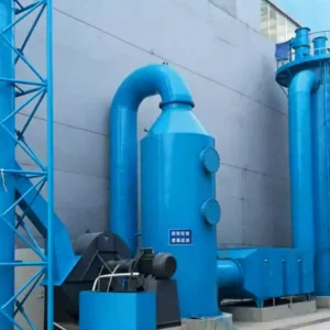
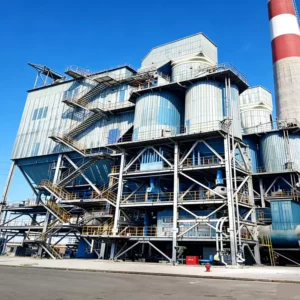
5.2 Project Completion Images
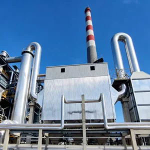
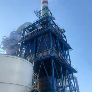
The following images document the completed flue gas purification facility and its operational status:

Figure 4: Completed Flue Gas Purification Facility at the Steel Manufacturing Site
5.3 Operational Images

Figure 5: DCS Control System Monitoring Interface for Real-Time Emission Management
5.4 Operational Risk Analysis
(1) Primary Operational Risks:
① Fluctuations in flue gas temperature, particulate matter, and sulfur dioxide concentrations can cause unstable system discharge performance.
② Malfunction of upstream dust removal equipment can lead to heat exchanger fouling and blockage due to excessive particulate loading.
③ Pipeline damage during production operations may result in wastewater overflow incidents.
④ Equipment and ductwork corrosion during production can reduce structural integrity and equipment strength.
(2) Mitigation Measures:
① Maintain close communication and information sharing between the flue gas purification system and production equipment. In the event of operational fluctuations, advance notification enables coordinated response.
② Install particulate concentration monitoring instruments at the MGGH heat exchanger cooling section inlet for real-time dust tracking, supplemented by ash removal devices operating continuously.
③ Strengthen personnel patrols and inspections to maintain normal equipment operation.
④ Continuously enhance the safety awareness and operational skills of relevant personnel, regularly revise safety measures and emergency plans to ensure effective incident response.
5.5 Key Technical Insights
The successful implementation of this project yields several valuable insights for similar steel industry flue gas treatment applications:
• Heat Recovery Integration: The MGGH heat exchanger system enables effective heat recovery from high-temperature flue gas, simultaneously addressing plume suppression requirements and reducing thermal energy losses. This approach exemplifies best practices in RTO thermal management for industrial exhaust streams.
• Corrosion Protection: The combination of acid gas scrubbing, temperature conditioning through MGGH, and corrosion-resistant materials (2205 stainless steel for WESP components) effectively addresses the aggressive corrosion environment characteristic of steel industry flue gas.
• Modular Redundancy: The dual-unit configuration for all critical rotating equipment ensures continuous operation during maintenance activities, achieving system availability exceeding 98%.
• Byproduct Valorization: The gypsum byproduct meets construction-grade specifications and has been successfully commercialized, partially offsetting operational costs.
• Intelligent Control: The integrated environmental management platform with real-time monitoring and predictive control capabilities ensures consistent emission compliance across variable operating conditions.
Záver
This case study demonstrates the successful application of integrated multi-pollutant flue gas treatment technology for steel manufacturing operations. The scrubbing tower deacidification, limestone-gypsum desulfurization, wet electrostatic precipitation, and MGGH heat recovery treatment train achieves comprehensive control of sulfur dioxide, acid gases, particulate matter, and visible plume phenomena while maintaining operational efficiency and economic viability.
The project validates the critical importance of process integration, heat recovery optimization, and corrosion-resistant design in addressing the complex emission challenges characteristic of steel industry rotary kiln operations. As environmental regulations continue to tighten and corporate sustainability commitments intensify, such integrated RTO systems for DeSOx and flue gas treatment solutions will become increasingly essential for steel producers seeking to balance environmental stewardship with operational competitiveness.
For organizations evaluating similar waste gas treatment investments within the steel, metallurgical, or heavy industrial sectors, this implementation provides a proven reference framework adaptable to diverse operational contexts. The technical insights and operational lessons documented herein offer valuable guidance for project planning, equipment selection, commissioning execution, and long-term performance optimization.
Related Resources & Solutions
- Regenerative Thermal Oxidizer (RTO) Systems — Comprehensive thermal oxidation solutions for VOC and HAP destruction
- Riešenia na úpravu plynov NOx — Advanced nitrogen oxide reduction technologies for industrial applications
- RTO Systems for DeSOx — Integrated desulfurization and thermal oxidation configurations
- Dust Collector Systems — High-efficiency particulate control for industrial exhaust streams
© Ever-power RTO Systems | Industrial Waste Gas Treatment Solutions
For technical inquiries: [SALES_EMAIL]