Investigate catalyst performance with evidence, not assumptions
Catalyst deactivation is a reduction in the ability of a catalyst to perform its intended role under specified conditions. In an RCO installation, an apparent decline may reflect chemical or physical changes to the catalyst, but it can also result from a changed exhaust stream, altered flow distribution, faulty instrumentation, or operation outside the original envelope. Diagnosis should separate these possibilities before replacement is authorized.
Define the symptom precisely. Has an emissions measurement changed, has the expected temperature profile shifted, has pressure drop risen, or has supplemental energy increased? These observations are related but not interchangeable. Higher energy use alone does not establish catalyst damage, and a pressure-drop increase may reflect deposits or a separate restriction. Record timing, operating mode, alarms, and the measurements associated with the change.
Use a structured maintenance approach →
Confirm the symptom
Compare like with like
Preserve the evidence
Separate possible causes before opening equipment
Review the process history around the first abnormal reading. New raw materials, solvent substitutions, coating changes, cleaning cycles, line speed, exhaust capture, dilution, or upstream maintenance can change the gas reaching the RCO. A catalyst suitable for the previous stream may face different chemistry after a production change. Ask operators what changed during the same period rather than assuming the oxidizer is the only possible cause.
Compare the current gas profile with the original design basis. Useful data include compound identity where known, concentration range, airflow, temperature, moisture, particulate, aerosols, and credible upset modes. If current data are missing, schedule representative sampling under the affected condition. A historical average may not help if the issue appears only during startup, changeover, or cleaning.
Validate the measurement chain before interpreting results. Confirm calibration status, sampling location, analyzer method, sample conditioning, instrument range, and recent maintenance. Compare independent measurements where the approved procedure allows it. A shifted sensor or inconsistent method can create the appearance of declining performance. Instrument checks must be performed by qualified personnel under site procedures, not by bypassing safeguards.
Pressure and temperature trends help localize an issue, but each measurement needs context. Rising differential pressure may indicate deposits, blocked passages, upstream filter loading, or changed flow. A shifted temperature profile may reflect VOC loading, heat input, leakage, sensor drift, or distribution. Compare several related measurements and the production timeline before attributing a trend to catalyst activity.
Physical fouling differs from chemical poisoning, although both may reduce effective catalyst performance. Dust, sticky aerosols, polymerizing material, or condensed high-boiling organics can mask active surfaces or obstruct channels. A chemically harmful compound may affect active sites without producing visible deposits. The diagnostic plan should consider both mechanisms; appearance alone cannot prove that a catalyst is healthy or failed.

Potential catalyst-sensitive constituents must be assessed against the actual formulation and exposure. Silicon-bearing species, sulfur compounds, halogens, certain metals, and process additives may warrant attention depending on chemical form and concentration. Avoid treating a generic list as a definitive diagnosis. Ask which compounds were evaluated and what sampling or testing could distinguish reversible fouling from persistent activity loss.
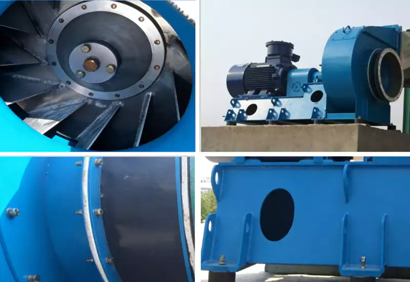
Operation outside the intended window can create an apparent performance decline. Changes in flow, temperature, oxygen availability, contact conditions, or distribution can reduce results even if catalyst material has not irreversibly changed. Review the control sequence, fan behavior, flow balance, and approved settings. Any adjustment should be authorized and recorded; do not compensate for unexplained drift by changing a protective limit.
Use the same measurement basis when comparing current performance with commissioning results. Feed composition, production rate, operating state, sampling duration, and analytical method should be comparable or their differences documented. A peak solvent event compared with a stable low-load baseline may not reveal catalyst condition. A valid baseline helps avoid false conclusions and unnecessary replacement.
Use a disciplined sequence to decide what action is justified
After collecting evidence, classify likely causes into practical groups: feed change, instrument or sampling issue, flow or distribution issue, upstream fouling, catalyst contamination, thermal exposure, control sequence, or unresolved. The categories can overlap. The purpose is to choose the next safe test and keep the investigation traceable, not to assign blame. Record evidence for each hypothesis and the observation that would weaken it.
| Observed symptom | Possible explanations | Evidence to check first |
|---|---|---|
| Outlet result changes | Feed composition, sampling, catalyst condition, flow distribution | Timeline, analyzer method, current gas profile |
| Pressure drop rises | Deposits, filter loading, restriction, changed flow | Differential-pressure trend, fan data, upstream inspection |
| Supplemental energy rises | Feed heat contribution, leaks, startup, control change | Operating mode, temperatures, flow and heat records |
| Temperature profile shifts | Feed change, sensor drift, leakage, distribution | Calibration, sensor comparison, control sequence |
| Issue follows a process change | New compound, additive, cleaning or production mode | Change record and sampling under affected condition |
Where the design permits, inspect upstream filters, separators, duct low points, and deposit-prone areas before disturbing catalyst modules. Follow isolation, cooling, gas-testing, and access requirements. Do not open a hot or potentially contaminated vessel based on a trend alone. Qualified staff who understand the equipment and site hazards should define the inspection scope.
If catalyst inspection or sampling is necessary, follow the supplier’s procedure and preserve module identity. Record position, deposits, damage, discoloration, channel condition, and samples taken. Photographs can support future comparison, but appearance does not replace an appropriate activity assessment where one is available. Store the method and interpretation with the service record.
Before replacing catalyst, ask whether upstream correction, process change control, flow correction, instrument repair, or approved cleaning is more appropriate. Some deposits cannot be removed safely or effectively, and some material damage is not reversible. Base the decision on supplier guidance, actual condition, required performance, and the risk of each option. Do not use an improvised chemical or mechanical cleaning method.
A six-step catalyst diagnostic sequence
After corrective work, repeat the measurements needed to demonstrate that the symptom has been addressed. Record the same feed conditions, temperatures, pressure behavior, analyzer basis, alarms, and operating mode used during diagnosis. If a performance test is required, use the agreed procedure. Return to normal operation should be documented as an observed result, not inferred from one favorable screen reading.
Prevention begins with process change management and trend review. Maintain a current list of feed compounds and additives, record changes in production or cleaning chemistry, and ensure operators know which changes require engineering review. Trend relevant variables and investigate gradual drift before it becomes a production emergency. Early investigation provides more opportunity to collect evidence under controlled conditions.
Review pressure-drop troubleshooting factors →
Spare catalyst planning should follow service conditions and documented supplier recommendations, not a universal replacement interval. If a spare set is justified, define storage conditions, packaging, module traceability, and allowable storage time. Establish the decision authority and replacement criteria. These records reduce the risk of installing the wrong material or treating a temporary process issue as catalyst end-of-life.
An effective incident report explains the symptom, operating context, measurement validation, candidate causes, inspections, corrective action, and follow-up result. Distinguish confirmed findings from hypotheses and identify missing data. The report becomes a reference for future maintenance and can reveal whether the plant needs better sampling, more complete trend data, or a clearer change-control trigger.
The most reliable diagnosis is a sequence rather than a single test. Start with the process timeline, confirm measurements, compare the feed envelope, review pressure and temperature trends, inspect upstream equipment, and involve the catalyst supplier when chemistry or material condition remains uncertain. This protects personnel, avoids premature replacement, and keeps the operating record defensible.
Close the investigation by updating the baseline and maintenance plan. If the root cause was a process change, ensure the design envelope and instructions reflect the approved change. If the cause remains uncertain, record the remaining question and next test rather than declaring the catalyst healthy or failed without evidence. The goal is a controlled decision that can be revisited when new data arrive.
 ZH
 EN
 ES
 AR
 ID
 PT
 FR
 JA
 RU
 DE
 MS
 CS
 BG
 NL
 KO
 RO
 SK
 TH
 VI
 ZH_TW
 UK