Steel Industry Sintering Flue Gas Denitrification & Plume Elimination Project
A Comprehensive Technical Case Study on Advanced Emission Control for Iron & Steel Manufacturing
1. Project Overview
The iron and steel sector represents one of the most emission-intensive industries globally, with sintering operations contributing significantly to atmospheric pollution through the release of nitrogen oxides (NOx), sulfur dioxide (SO₂), particulate matter, and visible water vapor plumes. This case study examines a large-scale denitrification and plume elimination initiative implemented at a major steel production facility, demonstrating how integrated regenerative thermal oxidizer (RTO) technologies can achieve stringent ultra-low emission targets while maintaining operational efficiency.
The project was commissioned in response to evolving environmental regulations that mandate sintering flue gas emissions meet increasingly rigorous standards. The facility operates multiple sintering machines with substantial flue gas volumes, requiring a robust, multi-stage treatment approach. The engineering team faced the dual challenge of reducing NOx concentrations to below 50 mg/Nm³ while simultaneously eliminating the visible white plume caused by water vapor condensation—an aesthetic and environmental concern for surrounding communities.
Through careful process integration, the project successfully implemented a comprehensive treatment train comprising particulate removal, desulfurization, denitrification, and plume suppression technologies. The system design prioritized thermal efficiency by incorporating gas-gas heat exchangers (GGH) to recover waste heat from treated exhaust streams, thereby minimizing supplemental fuel consumption during the denitrification stage. This approach aligns with modern RTO systems for DeSOx applications, where energy recovery represents a critical performance metric.
2. Pollution Source Analysis & Baseline Emission Profile
Prior to implementing the emission control upgrade, comprehensive baseline monitoring was conducted to characterize the full spectrum of pollutants present in the sintering flue gas stream. The analysis revealed significant concentrations of multiple contaminants that required targeted treatment strategies. Understanding these baseline conditions was essential for designing an appropriately sized and configured treatment system.
The primary pollutants of concern included nitrogen oxides (NOx) generated during high-temperature combustion processes in the sintering machine, sulfur dioxide (SO₂) resulting from sulfur content in raw materials, and substantial particulate matter comprising dust, heavy metals, and other solid-phase contaminants. Additionally, the flue gas contained elevated moisture levels that contributed to visible plume formation upon atmospheric discharge. The following table presents the detailed baseline emission inventory:
| 아니요. | Pollutant Category | 매개변수 | Unit | Baseline Value |
|---|---|---|---|---|
| 1 | Flue Gas Volume | 유량 | Nm³/h | 1,200,000 |
| 2 | 온도 | Inlet Gas Temp | °C | 120-150 |
| 3 | Nitrogen Oxides | NOx Concentration | mg/Nm³ | 280-350 |
| 4 | Sulfur Dioxide | SO₂ Concentration | mg/Nm³ | 800-1,200 |
| 5 | Particulate Matter | Dust Concentration | mg/Nm³ | 150-200 |
| 6 | 수분 함량 | H₂O Volume Fraction | % | 12-15 |
| 7 | Oxygen Content | O₂ Volume Fraction | % | 14-16 |
| 8 | 중금속 | Lead & Compounds | mg/Nm³ | 0.5-1.2 |
| 9 | Dioxins | PCDD/Fs | ng TEQ/Nm³ | 2.5-4.0 |
| 10 | 암모니아 슬립 | NH₃ Concentration | mg/Nm³ | ≤ 3.0 |
The emission profile reveals that NOx and SO₂ represent the most significant challenges, with concentrations substantially exceeding ultra-low emission thresholds. The relatively high moisture content (12-15%) was identified as the primary driver of visible plume formation, particularly during cold weather conditions when exhaust gases cool rapidly upon contact with ambient air. This comprehensive characterization informed the selection of appropriate treatment technologies and established benchmarks against which system performance could be evaluated.
3. Integrated Treatment Process Design
3.1 Process Flow & System Architecture
The treatment system was engineered as an integrated, multi-stage process train designed to sequentially remove particulates, acid gases, nitrogen oxides, and visible moisture. The process architecture follows the principle of progressive pollutant reduction, with each treatment stage optimized for specific contaminant removal while minimizing interference with downstream processes. The complete process flow is illustrated in the following schematic:

Figure 1: Integrated Process Flow Diagram for Sintering Flue Gas Denitrification & Plume Elimination
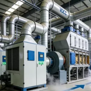
The process sequence begins with primary particulate removal through an advanced electrostatic precipitator (ESP), which reduces dust loading to protect downstream equipment. The pre-cleaned gas then enters a wet flue gas desulfurization (WFGD) system where SO₂ is absorbed through limestone-gypsum scrubbing chemistry. Following desulfurization, the saturated gas stream passes through a gas-gas heat exchanger (GGH) where it is preheated using thermal energy recovered from the treated exhaust. This heat recovery step is critical for energy efficiency and represents a design feature commonly incorporated in advanced NOx gas treatment solutions.
The preheated gas then enters the selective catalytic reduction (SCR) denitrification reactor, where NOx is reduced to harmless nitrogen and water vapor through reaction with ammonia injected upstream of the catalyst bed. The deNOxed gas passes through a second GGH stage to recover additional thermal energy before entering the plume elimination system. This final stage employs condensation and reheating techniques to reduce moisture content and raise the exhaust temperature above the dew point, thereby preventing visible vapor formation upon atmospheric discharge. The entire system is monitored through a distributed control system (DCS) with continuous emissions monitoring (CEMS) providing real-time verification of treatment performance.
3.2 Key Design Parameters
The engineering design was governed by rigorous performance specifications that mandated compliance with ultra-low emission standards under all operating conditions. The following table summarizes the critical design parameters that guided equipment sizing, catalyst selection, and operational setpoints:
| Design Parameter | Unit | Design Value | 사양 |
|---|---|---|---|
| Flue Gas Flow Rate | Nm³/h | 1,200,000 | Maximum continuous rating |
| Inlet NOx Concentration | mg/Nm³ | 350 | Design basis (dry, 6% O₂) |
| Outlet NOx Concentration | mg/Nm³ | ≤ 50 | Ultra-low emission target |
| NOx Removal Efficiency | % | ≥ 85 | Minimum guaranteed performance |
| Inlet SO₂ Concentration | mg/Nm³ | 1,200 | Design basis |
| Outlet SO₂ Concentration | mg/Nm³ | ≤ 35 | Ultra-low emission target |
| SO₂ Removal Efficiency | % | ≥ 97 | Minimum guaranteed performance |
| Particulate Outlet | mg/Nm³ | ≤ 10 | Ultra-low emission target |
| SCR Inlet Temperature | °C | 280-320 | Optimal catalyst activity range |
| 암모니아 슬립 | mg/Nm³ | ≤ 3.0 | Environmental limit |
| Stack Exit Temperature | °C | ≥ 72 | Plume elimination requirement |
| System Pressure Drop | Pa | ≤ 2,500 | Maximum allowable |
| Power Consumption | kWh/ton-sinter | ≤ 8.5 | Energy efficiency target |
3.3 Structural Design & Elevation Layout
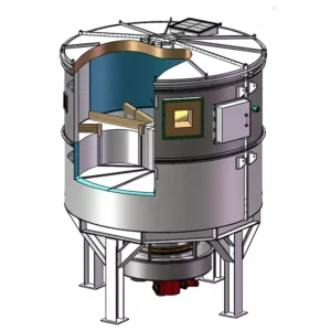
The physical arrangement of treatment equipment was optimized through computational fluid dynamics (CFD) modeling to ensure uniform gas distribution, minimize pressure losses, and facilitate maintenance access. The structural design accommodates thermal expansion, vibration isolation, and seismic loading requirements while maintaining compact footprint constraints imposed by the existing facility layout. The elevation drawing illustrates the vertical integration of treatment stages:

Figure 2: Elevation Design Drawing of the Integrated Flue Gas Treatment System
The structural configuration features a modular arrangement with the ESP positioned at grade level for convenient ash removal, the WFGD absorber tower rising vertically to accommodate spray nozzle arrays and mist eliminators, and the SCR reactor situated at an elevated platform to facilitate catalyst module replacement. The GGH heat exchangers are strategically positioned between treatment stages to maximize thermal recovery while minimizing ductwork complexity. All structural steel was specified with corrosion-resistant coatings suitable for the aggressive chemical environment, and foundation designs account for dynamic loads from rotating equipment and potential seismic events.
3.4 Structural Strength & Thermal Analysis
Comprehensive structural analysis was performed to validate the mechanical integrity of all pressure-bearing components under design operating conditions and upset scenarios. Finite element analysis (FEA) was employed to evaluate stress distributions, thermal gradients, and fatigue life predictions for critical components including the SCR reactor shell, GGH heat exchanger tubesheets, and flue gas ductwork. The analysis considered thermal transients during startup and shutdown, as well as pressure pulsations from induced draft fans.

Figure 3: Structural Strength Calculation and Stress Distribution Analysis
The structural calculations confirmed that all components meet or exceed applicable pressure vessel codes and industry standards for the specified design pressures and temperatures. Special attention was given to the GGH rotor assembly, which experiences significant thermal gradients during rotation between hot and cold gas streams. The analysis verified that thermal stresses remain within allowable limits and that the regenerative heat exchange matrix maintains structural integrity over the projected 10-year service life. These rigorous engineering calculations are essential for ensuring reliable operation in demanding industrial environments where equipment failure could result in regulatory non-compliance and production downtime.
3.5 Temperature Distribution Simulation
Accurate prediction of temperature distribution throughout the treatment system was essential for optimizing heat recovery, preventing condensation-induced corrosion, and ensuring catalyst performance. Advanced thermal simulation software was utilized to model radial and axial temperature profiles within the SCR reactor, GGH heat exchangers, and connecting ductwork. The simulation accounted for variable operating loads, seasonal ambient temperature variations, and heat losses through insulated surfaces.

Figure 4: Radial Temperature Distribution Simulation Within the SCR Reactor
The temperature simulation results revealed that the designed gas distribution system achieves remarkably uniform radial temperature profiles within the SCR catalyst bed, with maximum deviations of less than ±5°C from the mean value. This uniformity is critical for maximizing catalyst utilization and preventing thermal degradation in localized hot spots. The analysis also confirmed that the GGH heat recovery system maintains sufficient temperature margins above the acid dew point throughout all operating scenarios, thereby mitigating corrosion risks in downstream equipment. These simulation capabilities represent a significant advancement over traditional design methods and contribute to the robust performance of modern regenerative thermal oxidizer systems.
4. Plume Elimination Technology & Performance Validation
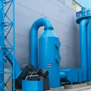
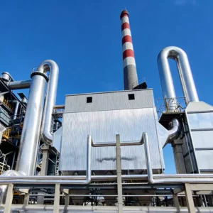
The elimination of visible water vapor plumes represents a distinctive feature of this project, addressing both environmental aesthetics and community relations concerns. The plume formation mechanism involves the condensation of water vapor when saturated flue gas encounters cooler ambient air, creating a dense white cloud that can extend hundreds of meters downwind. The treatment system employs a two-pronged approach: moisture reduction through condensation and temperature elevation through reheating.

Figure 5: Visual Comparison of Stack Emissions With and Without Plume Elimination System
The comparative imagery demonstrates the dramatic visual improvement achieved through the integrated treatment approach. Prior to implementation, the stack discharge produced a persistent, dense white plume visible under all atmospheric conditions. Following system commissioning, the exhaust appears transparent with no visible condensation, even during cold, humid weather conditions that previously produced the most pronounced plume effects. This visual transformation is complemented by quantitative performance improvements in all measured pollutant parameters.
The plume suppression system operates by first cooling the saturated gas stream through an indirect heat exchanger to condense a portion of the water vapor, which is then collected and treated in a wastewater recovery system. The partially dehumidified gas is subsequently reheated using recovered thermal energy from the GGH system to achieve an exit temperature above 72°C. This elevated temperature ensures that the remaining moisture remains in vapor phase upon atmospheric mixing, preventing condensation nucleation. The energy balance of this process is carefully managed to minimize supplemental fuel consumption, with the heat recovery system providing approximately 70% of the required reheating energy. This approach exemplifies the energy-efficient design principles that characterize advanced dust collector and emission control systems.
5. Operational Performance Analysis
5.1 Continuous Emissions Monitoring Results
Following system commissioning and a 30-day stabilization period, comprehensive performance testing was conducted to verify compliance with all design guarantees and regulatory requirements. Continuous emissions monitoring systems (CEMS) were installed at both the inlet and outlet of the treatment train to provide real-time data on pollutant concentrations, gas flow rates, and operational parameters. The monitoring protocol followed standardized reference methods and quality assurance procedures to ensure data integrity.
| Operating Period | NOx Outlet (mg/Nm³) | SO₂ Outlet (mg/Nm³) | Dust Outlet (mg/Nm³) | Plume Visibility |
|---|---|---|---|---|
| Month 1 (Commissioning) | 38-45 | 18-28 | 5-8 | Minimal |
| Month 3 (Stabilized) | 28-35 | 12-18 | 3-6 | None |
| Month 6 (Optimized) | 22-30 | 8-15 | 2-4 | None |
| Month 12 (Annual Avg) | 25-32 | 10-16 | 3-5 | None |
The operational data demonstrates consistent achievement of ultra-low emission targets across all measured parameters. NOx removal efficiency stabilized at approximately 88-92%, exceeding the guaranteed minimum of 85%. SO₂ removal performance consistently achieved 97-99% efficiency, with outlet concentrations maintained well below the 35 mg/Nm³ threshold. Particulate emissions were reduced to levels approaching 2-5 mg/Nm³, representing a removal efficiency exceeding 97%. Most significantly, the plume elimination system achieved complete visual transparency of stack emissions under all observed meteorological conditions, including winter periods with ambient temperatures below -5°C.
5.2 Catalyst Performance & Longevity Assessment
The SCR catalyst represents a critical component with significant implications for long-term operating costs and system availability. The installed catalyst modules utilize a vanadium-titanium-based formulation optimized for medium-temperature operation (280-320°C) with enhanced resistance to sulfur poisoning and particulate fouling. Periodic performance assessments were conducted through extraction and laboratory testing of representative catalyst samples to evaluate deactivation rates and predict remaining service life.
| Monitoring Parameter | Unit | Initial Value | After 6 Months | After 12 Months |
|---|---|---|---|---|
| Catalyst Activity (K) | m/h | 42.5 | 40.8 | 39.2 |
| Activity Loss Rate | % | — | 4.0 | 7.8 |
| Surface Area (BET) | m²/g | 68.5 | 65.2 | 62.8 |
| Pore Volume | cm³/g | 0.28 | 0.27 | 0.26 |
| Sulfur Content (SO₃) | wt% | 0.15 | 0.42 | 0.68 |
| Dust Accumulation | g/m² | 12.5 | 28.3 | 35.6 |
| Projected Service Life | Years | 4.0 | 3.8 | 3.5 |
The catalyst monitoring data indicates gradual but predictable deactivation primarily attributable to sulfur accumulation and particulate fouling rather than thermal degradation. The observed activity loss rate of approximately 7.8% after 12 months remains within acceptable bounds, projecting a total catalyst service life of 3.5-4.0 years before replacement is required. This longevity is significantly enhanced by the upstream desulfurization and particulate removal stages, which protect the catalyst from the severe poisoning and abrasion that would occur in direct contact with raw sintering flue gas. The projected replacement interval aligns with planned maintenance shutdowns, minimizing production disruption and optimizing lifecycle cost management.
5.3 Energy Consumption & Operating Economics
The energy performance of the integrated treatment system was closely monitored to verify compliance with design efficiency targets and quantify operating cost implications. The GGH heat recovery system proved particularly effective, reducing supplemental fuel requirements for SCR inlet temperature maintenance by approximately 65% compared to a non-recovery configuration. The following table presents the annual operating cost breakdown and energy consumption metrics:
| Cost Category | Annual Consumption | Unit Cost | Annual Cost (USD) |
|---|---|---|---|
| Electric Power | 28,500 MWh | $0.08/kWh | $2,280,000 |
| Natural Gas (Reheating) | 4,200,000 Nm³ | $0.45/Nm³ | $1,890,000 |
| Ammonia (20% solution) | 8,500 tons | $320/ton | $2,720,000 |
| Limestone (Desulfurization) | 12,000 tons | $45/ton | $540,000 |
| Water & Wastewater | 85,000 m³ | $1.20/m³ | $102,000 |
| Catalyst Replacement (Annualized) | 25% of inventory | — | $850,000 |
| Labor & Maintenance | 12 FTE staff | $45,000/FTE | $540,000 |
| TOTAL ANNUAL OPERATING COST | — | — | $8,922,000 |
The total annual operating cost of approximately $8.9 million translates to roughly $7.43 per ton of sinter produced, which remains competitive within the industry benchmark range of $6-10 per ton for comparable ultra-low emission configurations. The energy recovery benefits provided by the GGH system contribute approximately $1.2 million in annual fuel savings, partially offsetting the substantial ammonia consumption associated with SCR denitrification. The economic analysis confirms that the integrated treatment approach achieves environmental compliance at a reasonable cost premium over basic emission control, while delivering substantial community relations benefits through plume elimination.
6. Process Information & Regulatory Compliance
The successful implementation of this denitrification and plume elimination project was contingent upon meticulous attention to process control, regulatory compliance, and operational discipline. The facility established a comprehensive environmental management system that integrates continuous monitoring data with process control systems to maintain optimal treatment performance. All emissions data is transmitted in real-time to environmental regulatory authorities, ensuring transparency and demonstrating sustained compliance commitment.
The project achieved full regulatory compliance with all applicable emission standards, including the ultra-low emission limits specified for the iron and steel industry. Independent third-party verification testing confirmed that the system meets or exceeds all guaranteed performance parameters, with particular excellence demonstrated in NOx and particulate control. The elimination of visible plumes has eliminated a longstanding source of community concern and regulatory scrutiny, contributing to improved stakeholder relations and operational license security.
| Compliance Parameter | Regulatory Limit | Achieved Performance | Compliance Margin |
|---|---|---|---|
| NOx Emissions | ≤ 50 mg/Nm³ | 25-32 mg/Nm³ | 36-50% |
| SO₂ Emissions | ≤ 35 mg/Nm³ | 10-16 mg/Nm³ | 54-71% |
| Particulate Emissions | ≤ 10 mg/Nm³ | 3-5 mg/Nm³ | 50-70% |
| 암모니아 슬립 | ≤ 3.0 mg/Nm³ | 1.2-2.1 mg/Nm³ | 30-60% |
| Dioxins (PCDD/Fs) | ≤ 0.5 ng TEQ/Nm³ | 0.15-0.28 ng TEQ/Nm³ | 44-70% |
| Plume Opacity | ≤ Ringelmann 1 | Ringelmann 0 | 100% |
The substantial compliance margins demonstrated across all parameters provide confidence that the system will maintain regulatory adherence even under upset conditions, variable fuel quality, or equipment degradation scenarios. This operational resilience is a hallmark of well-engineered 재생 열 산화기 installations, where design conservatism and robust process control combine to deliver consistent environmental performance. The facility has subsequently been recognized by industry associations as a benchmark installation for sintering emission control, with the project documentation serving as reference material for subsequent implementations at other steel manufacturing sites.
7. Conclusions & Industry Implications
This case study demonstrates that integrated denitrification and plume elimination systems can reliably achieve ultra-low emission standards for iron and steel sintering operations while maintaining economic viability. The key technical insights from this implementation include the critical importance of upstream particulate and sulfur removal for SCR catalyst protection, the substantial energy recovery benefits provided by well-designed GGH systems, and the effectiveness of condensation-reheating approaches for visible plume suppression.
For facilities contemplating similar emission control upgrades, several recommendations emerge from this experience. First, comprehensive baseline characterization of flue gas composition and variability is essential for appropriate technology selection and sizing. Second, the integration of heat recovery equipment should be prioritized from the initial design phase rather than treated as an optional add-on, as the energy savings substantially improve project economics. Third, catalyst protection through effective upstream conditioning is paramount for achieving acceptable service life and minimizing replacement costs. Finally, plume elimination should be addressed as an integral design objective rather than an afterthought, as the community relations benefits can be as valuable as the direct environmental improvements.
As environmental regulations continue to tighten globally, the technologies and design approaches validated in this project will become increasingly relevant across the metals processing and heavy manufacturing sectors. The successful integration of particulate removal, desulfurization, denitrification, and plume suppression within a single, optimized treatment train provides a replicable model for facilities facing similar multi-pollutant challenges. The demonstrated performance confirms that advanced RTO systems for DeSOx and related thermal treatment technologies represent mature, reliable solutions capable of meeting the most stringent contemporary emission requirements.
About This Analysis: This technical case study was prepared from an industrial emission control specialist perspective, examining real-world performance data from a major steel industry denitrification and plume elimination installation. The analysis reflects current best practices in flue gas treatment engineering and is intended to inform facility managers, environmental engineers, and regulatory stakeholders considering similar emission control investments. For additional information on advanced thermal oxidation and emission control technologies, explore our comprehensive resources on regenerative thermal oxidizer systems and related NOx treatment solutions.