Understand RCO as a complete process, not just a catalyst bed
Regenerative Catalytic Oxidation is a treatment approach for suitable volatile organic compound streams in which catalytic oxidation is integrated with regenerative heat management. It is not one universal vessel arrangement. Designs can organize chambers, valves, catalyst sections, and heat-storage media differently, so the engineering description should follow the project’s process-flow diagram and control narrative.
The gas path and energy path are related but should be understood separately. The gas path describes where exhaust travels, what it contacts, and where treated gas leaves the system. The energy path describes how heat is stored and returned to incoming gas, how supplemental input is managed, and where losses occur. Separating the two helps explain performance without confusing process flow with heat recovery.
Review regenerative heat-recovery factors →
Collect and condition
Transfer heat and oxidize
Monitor the envelope
Follow the gas path and energy path separately
Exhaust collection begins at the source. Capture hoods, enclosures, duct branches, balancing devices, and fans influence the flow and composition arriving at the oxidizer. If collection is inconsistent, the treatment unit may receive a stream that differs from its design basis. Review the capture network alongside the oxidizer, including production-mode changes, dilution, and any intentional bypass arrangement.
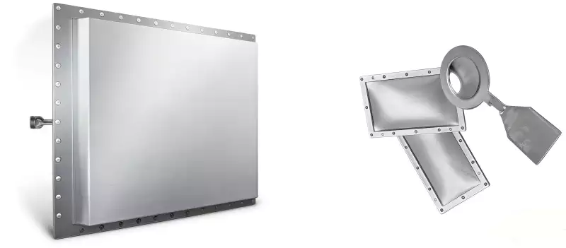
Before gas reaches the catalyst, the project may require conditioning or pretreatment. The need depends on particulate, droplets, sticky or condensable organics, moisture, corrosive constituents, and catalyst-sensitive compounds. Some streams may need little additional conditioning; others require a defined removal step. The choice should follow sampling and supplier review rather than a blanket claim that every RCO needs identical upstream equipment.
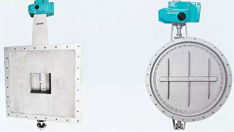
Regenerative heat transfer uses hot treated gas to warm incoming exhaust through heat-storage surfaces. The cycle depends on the selected architecture. In switching-bed arrangements, flow paths change according to a control sequence; other systems use different distribution or rotation methods. The design review should explain heat transfer under the required flow envelope and address switching, leakage, pressure drop, and abnormal operation.
The catalytic section provides an active surface that promotes oxidation for compatible compounds under specified conditions. It is not a universal filter or a substitute for understanding chemistry. Catalyst performance depends on the gas composition and operating window, and some contaminants can reduce activity or create deposits. The process narrative should identify the compounds evaluated and the conditions outside the approved envelope.
Oxidation behavior depends on compound identity, oxygen availability, temperature, contact conditions, and catalyst characteristics. The performance target must be defined for the application and verified using the agreed test method. Do not assume every compound behaves identically or that one generic temperature guarantees the same result for every mixture. Process-specific validation remains central to defensible emissions control.
Heat leaving the oxidation zone contributes to the regenerative cycle, while losses and changing process loads affect the net balance. A stream that differs from the design assumption can change supplemental-energy needs. Frequent starts, low-load operation, and long idle periods also influence energy use. A useful process description identifies the operating cases included in estimates rather than presenting only a steady-state figure.
Controls coordinate equipment sequence with process conditions. Depending on the design, monitored variables may include flow, selected temperatures, pressure, fan status, valve position, heat-input status, and emissions-related measurements. The exact instrument list must come from the approved control design. Operators need to know what each signal means, which alarms require action, and which conditions prevent startup or require a controlled shutdown.
Safety functions depend on the actual exhaust hazards, including flammability, oxygen, concentration variability, loss of flow, and credible process upsets. The safety basis should define required permissives, trips, interlocks, and responses. A process-flow diagram alone cannot establish safe operating logic. The commissioning team should verify the approved sequence and document each required test before routine operation.
Controls connect process conditions with safe operation
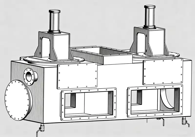
The equipment boundary should be explicit. It may include inlet ductwork, dampers, fans, pretreatment, regenerative chambers or rotor, catalyst modules, heat input, controls, stack, sampling ports, access platforms, and utilities. Not every project includes every item. Clear boundaries prevent misunderstandings when proposals compare performance, energy, pressure drop, or maintenance responsibilities.
| Process stage | Main question | Evidence to review |
|---|---|---|
| Exhaust capture | Does the unit receive intended flow and composition? | Capture layout, flow data, operating modes |
| Pretreatment | Which contaminants need control? | Sampling, separator basis, maintenance plan |
| Regenerative section | How is heat transferred and flow routed? | Process diagram, valve or rotor sequence |
| Catalyst section | Which compounds and conditions are covered? | Compatibility review, envelope, inspection plan |
| Discharge and verification | How is performance demonstrated? | Sampling ports, test method, acceptance criteria |
Heat recovery should be assessed using consistent assumptions for inlet flow, temperature, VOC profile, operating schedule, and equipment boundary. If one estimate excludes startup energy or fan electricity while another includes it, the figures are not directly comparable. Request the operating cases and clarify whether secondary heat use outside the oxidizer is included or reported separately.
Pressure drop is a system-level characteristic. Regenerative media, catalyst, duct transitions, pretreatment, dampers, and stack components can all contribute resistance. A rise in differential pressure may indicate deposits, changing flow, a sensor problem, or another restriction, but it does not identify the cause alone. Trend readings alongside fan behavior and process output before choosing a maintenance action.
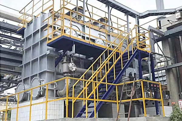
Commissioning turns the process narrative into an operating baseline. The team should confirm instrument calibration, valve or rotor sequence, fan direction, interlock logic, temperature response, sampling locations, and the performance-test plan. The exact checklist depends on the approved design and local requirements. Items that cannot be demonstrated should be recorded and resolved rather than assumed complete because the equipment has started.
A six-step process review before commissioning
Operators need a practical explanation of normal operation and abnormal response. This includes startup prerequisites, expected trends, alarm meanings, prohibited adjustments, and the people authorized to change settings. A control screen can display many values without making the process understandable. Training should connect each critical signal to an operating decision and the limits that require escalation.
Routine monitoring needs context. Record operating mode, product or recipe, flow, relevant temperatures, pressure behavior, heat input, alarms, and unusual events according to the approved procedure. A reading without context can mislead: a temperature shift during a product change may differ from the same shift at stable throughput. Trend interpretation should start with the process timeline.
Compare regenerative bed arrangements →
Maintenance tasks should reflect the architecture. Switching arrangements may require attention to valves, seals, actuators, and purge behavior; rotating systems have their own mechanical and sealing needs; all designs require suitable inspection of fans, instruments, access points, and catalyst condition. Follow the supplier’s approved instructions and site safety procedure rather than borrowing an interval from a different layout.
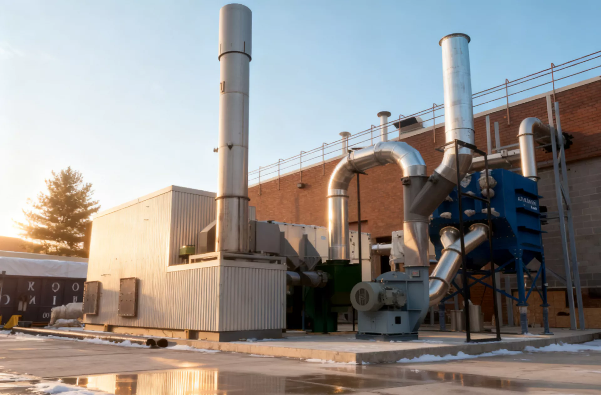
Process changes should be reviewed against the original design envelope. New solvents, coatings, binders, cleaning agents, production speeds, or capture changes can alter the conditions seen by the catalyst. Document the change, determine whether sampling is needed, and review controls and safety before the new mode becomes routine. This is especially important when compatibility was reviewed against a defined compound list.
A good process description lets an engineer trace the gas path, understand heat recovery, identify the catalyst’s role, and explain how controls detect abnormal conditions. It also shows what lies outside the package boundary. This makes design review more practical, supports operator training, and gives commissioning staff a common reference when measurements do not match the expected sequence.
For procurement and operations, request the process-flow diagram, equipment boundary, control narrative, instrument list, safety permissives, design-case data, and acceptance plan as coordinated documents. When these records agree, the plant can connect the intended design with the installed system and its maintenance plan. When they conflict, resolve the difference before relying on an energy estimate or performance promise.
 ES
 EN
 ZH
 AR
 ID
 PT
 FR
 JA
 RU
 DE
 MS
 CS
 BG
 NL
 KO
 RO
 SK
 TH
 VI
 ZH_TW
 UK