
Review the concentrator and RCO as one connected process
A zeolite concentrator and an RCO perform different but connected jobs. The concentrator can capture suitable VOCs from a larger exhaust volume and release them in a smaller, more concentrated stream for downstream treatment. That changes the gas flow, concentration profile, and heat balance seen by the RCO. The integration should be evaluated using actual adsorption and desorption cycles, not a single average taken from the original dilute exhaust.
Start by drawing the two gas paths separately. Identify the process exhaust entering the concentrator, treated air leaving it, the desorption stream, and the route from desorption to the RCO. Mark fans, dampers, heating sources, purge or cooling steps where fitted, measurement points, and any bypass or isolation arrangement. The drawing should match the proposed equipment architecture; not every concentrator uses the same sequence or control arrangement. low-concentration VOC treatment factors provides a related technical reference for this decision.
Map adsorption and desorption before calculating energy
The concentrator inlet stream needs its own characterization. Record flow range, temperature, humidity, VOC composition, particles, aerosols, and possible compounds that can affect adsorption performance. A concentrator is not a universal solution for every gas, and adsorbent suitability depends on actual chemistry and operating conditions. Do not assume zeolite means all VOCs will be captured equally or that contaminants are automatically removed.
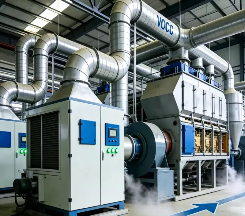
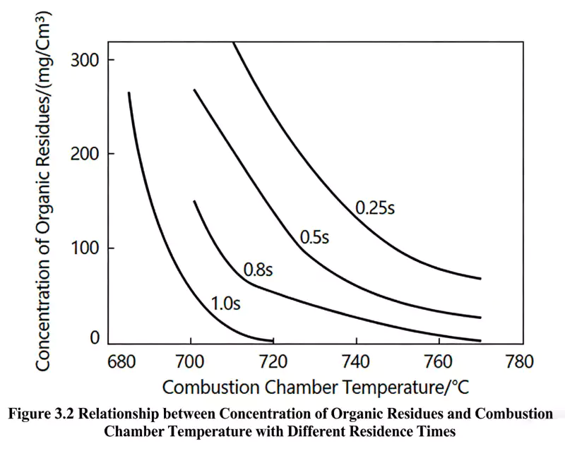
The desorption stream is often smaller than the inlet stream, but its concentration and temperature may vary over the cycle. Record the start and end of desorption, peak and typical concentration, flow, temperature, and transition conditions. A cycle-average value can hide a short peak that matters to the RCO’s approved operating envelope. Use time-based measurements or a justified profile where necessary, and state what has actually been measured.
The RCO catalyst must be reviewed against the concentrated mixture, not merely the dilute inlet sample. Concentration changes can alter the thermal contribution and may expose the catalyst to a different peak condition. Chemical compatibility still depends on compound identity and other constituents. Ask the supplier to evaluate the desorption composition, peak ranges, oxygen conditions, and unresolved compounds, and identify additional sampling needed before the integrated design is finalized.
Energy analysis should separate concentrator energy from oxidizer energy. The concentrator may require energy for desorption or other cycle steps, while the RCO has its own heat recovery and supplemental-energy behavior. A combined estimate should state which utilities are included and which operating cases are represented. Avoid comparing an integrated system’s total energy with an RCO-only estimate; the boundaries must match for the comparison to be meaningful.
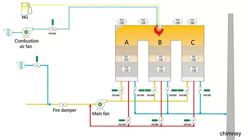
Heat recovery in the RCO should be modeled using the concentrated feed profile where appropriate. VOC heat contribution may vary during desorption, and flow and temperature may differ from the dilute stream. Evaluate the system across normal cycling, startup, low-load conditions, and credible peak cases. Ask for assumptions behind energy estimates and do not treat one steady-state value as a guarantee for every concentrator cycle.
Adsorption and desorption controls need a defined interface. Depending on the design, the RCO may need a readiness permissive before desorption is directed to it. The exact logic must follow the approved hazard review and supplier control narrative. Document what happens if the RCO is unavailable, a fan fails, a damper does not reach position, or desorption begins outside the intended sequence. Do not improvise a bypass to avoid an interlock.
Define the integrated operating envelope and control responsibilities
The integrated safety review should consider how concentration changes affect downstream equipment. Evaluate the actual flammability basis, oxygen conditions, temperature range, flow transitions, and credible faults with qualified personnel. Do not derive a protective limit from the nominal concentrator ratio alone. A ratio describes a process relationship; it does not replace measurement, hazard analysis, or the approved operating limits for the connected treatment system.
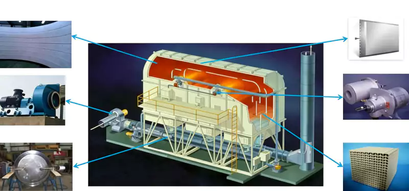
Pressure drop and fan duty should be reviewed across both units and connecting ductwork. The concentrator, filters, dampers, RCO regenerative section, catalyst, and stack all contribute to system resistance. A fan selected for the original dilute exhaust may not suit a modified arrangement. Verify the intended operating point and determine which pressure measurements will help operators locate a restriction without dismantling the wrong component. For related design context, see RCO process sequence.
| Integration topic | Evidence to request | Question answered |
|---|---|---|
| Adsorption inlet | Flow, temperature, humidity, chemistry, physical contaminants | Is the concentrator suitable for the source stream? |
| Desorption cycle | Time-based flow, concentration, temperature and transitions | What does the RCO actually receive? |
| Catalyst compatibility | Compound list, peak exposure, supplier review | Is the downstream catalyst appropriate? |
| Controls interface | Readiness, fan and damper feedback, fault response | What happens when either package is unavailable? |
| Energy and acceptance | Shared boundary, operating cases, test plan | Can proposals be compared on equivalent evidence? |
Pretreatment may be needed upstream of the concentrator, between the concentrator and RCO, or at other points depending on the process. Its purpose should be explicit: protect adsorption performance, prevent physical deposits, or manage a defined contaminant. A particle filter cannot be credited with removing an unidentified gas-phase catalyst poison. Ask each supplier what the device removes, what remains, and how maintenance will be monitored.
A useful integration specification lists design cases for the full cycle. Include adsorption flow, treated outlet conditions, desorption flow and concentration profile, temperatures, known contaminants, start-stop sequence, and any condition when the RCO cannot accept the stream. Identify which data are measured and which are estimates. This makes it easier to identify missing evidence and compare proposals that otherwise use different assumptions about concentrator operation.
Vendor scope should cover the interface between packages. Clarify who supplies connecting ducts, fans, dampers, instruments, control communications, isolation, utilities, access, sampling points, and commissioning tests. If each supplier assumes the other owns an interlock or measurement, the plant may discover the gap during startup. A responsibility matrix should assign each interface to one party and define the evidence required for acceptance.
A practical review sequence
Commissioning should test the integrated sequence, not just each machine separately. Verify the concentrator’s intended cycle, flow and temperature signals, RCO readiness, damper or valve feedback where fitted, alarm and trip responses, and approved performance-test conditions. Record the desorption phase and feed profile during relevant tests. If the planned cycle cannot be reproduced, document the limitation and agree the next test rather than claiming the full envelope is validated.
After startup, trend variables from both systems on a shared timeline. Relevant data may include adsorption and desorption state, flow, temperatures, VOC measurements where available, RCO pressure behavior, supplemental heat, alarms, and process mode. A synchronized record can reveal whether a change begins in the concentrator cycle or downstream treatment. Separate logs that use different clocks or omit cycle state are much harder to interpret.
Maintenance responsibilities should be coordinated across the package boundary. The concentrator may have its own adsorbent, seals, drive or switching components depending on architecture; the RCO has catalyst and regenerative equipment requirements. Follow respective suppliers’ instructions and establish who investigates a change in desorption performance that later appears as an RCO issue. Do not assume one unit’s maintenance record fully explains the other’s behavior.
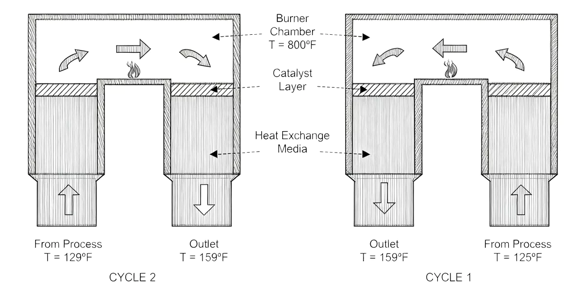
Process changes should be reviewed across the integrated system. New solvents, altered exhaust flow, changes in production schedule, or a modified adsorption cycle can change the desorption profile. Compare the proposed change with the original concentrator and RCO envelopes. If it falls outside the reviewed range, determine whether sampling, supplier review, or updated control logic is needed before adopting it in routine production.
Acceptance criteria should identify what the project is trying to demonstrate: concentrator operation, RCO emissions performance, integrated sequence, energy assumptions, or a combination. These are related but distinct checks. Define sampling methods, operating conditions, reporting basis, and sign-off responsibility before the test. Do not assume a successful single-unit test proves the complete system works under every combined cycle. Before freezing the scope, review catalyst compatibility criteria with the team responsible for the operating envelope.
常見問題
Does a zeolite concentrator guarantee a stable RCO inlet?
Can the catalyst be selected from the dilute inlet sample?
Should the two suppliers provide one combined energy figure?
What if the RCO is unavailable during desorption?
What data are most useful during commissioning?
Bring the source profile, time-based desorption data, package-boundary matrix, and integrated test plan into the same design review.
 ZH_TW
 EN
 ZH
 ES
 AR
 ID
 PT
 FR
 JA
 RU
 DE
 MS
 CS
 BG
 NL
 KO
 RO
 SK
 TH
 VI
 UK