High-Performance Lithium-Ion Battery Anode Material Graphitization Industry: Dust Removal, Desulfurization & Denitrification Project
A Comprehensive Technical Case Study on Advanced Multi-Pollutant Emission Control for Graphitization Furnace Operations
1. Project Overview
1.1 Background & Industry Context
The global transition toward electrified transportation and renewable energy storage has catalyzed unprecedented growth in the lithium-ion battery manufacturing sector. Within this rapidly expanding industry, the production of high-performance anode materials—specifically graphitized carbon products—represents a critical and technically demanding manufacturing stage. Graphitization, the high-temperature thermal treatment process that converts amorphous carbon into crystalline graphite structures, generates complex flue gas emissions requiring sophisticated multi-pollutant control strategies to meet increasingly stringent environmental standards.
The year 2023 witnessed global shipments of lithium-ion battery anode materials reaching 1.783 million tons, representing a year-over-year increase of 15.1%. Industry projections indicate this volume will exceed 8 million tons by 2030, driven by sustained growth in electric vehicle adoption, grid-scale energy storage deployment, and consumer electronics demand. This exponential market expansion has intensified regulatory scrutiny of graphitization operations, which historically represented a significant source of atmospheric emissions including sulfur dioxide, nitrogen oxides, particulate matter, and visible water vapor plumes.
In response to the “carbon peak and carbon neutrality” policy framework and the implementation of the 2024 July “Pollution Discharge Permit Management Measures” alongside the “Accelerated Construction of Carbon Emission Dual-Control System Work Plan,” the graphitization industry faces mounting pressure to achieve ultra-low emission performance. These regulatory developments have created substantial market demand for advanced flue gas purification systems capable of addressing the unique emission characteristics of graphitization furnace operations while maintaining production efficiency and economic viability.
1.2 Enterprise Profile
The subject enterprise specializes in the research, development, production, and sales of new energy lithium-ion battery anode materials, with its headquarters strategically located in Qionglai City, Chengdu, Sichuan Province. The facility leverages regional advantages in energy availability, labor resources, transportation infrastructure, and policy support to serve both domestic and international new energy markets. The company has established itself as a core supplier within the global anode material supply chain, with products exported to high-end customers across multiple continents.
The enterprise’s business portfolio encompasses the complete production chain of lithium-ion battery anode materials and graphitization-related products, with manufacturing operations spanning raw material processing, graphitization treatment, and finished product finishing. The facility has secured inclusion among the top three global anode material suppliers and maintains an extensive intellectual property portfolio comprising one enterprise brand project, two registered trademarks, and nineteen patents. The company’s commitment to technological innovation and environmental stewardship has positioned it as an industry leader in sustainable manufacturing practices.
This project addresses the critical environmental challenge of graphitization furnace flue gas treatment, which has become increasingly urgent under current regulatory frameworks. The implemented solution integrates three core technological approaches: advanced energy conversion and recovery systems to minimize thermal losses, mature limestone-gypsum wet desulfurization processes for high-efficiency SO₂ removal, and magnetic energy plume elimination technology for comprehensive pollutant deep purification. This integrated approach ensures that treated emissions meet the most stringent ultra-low emission standards while achieving complete visual transparency of stack discharge.
2. Pollution Source Analysis & Baseline Emission Profile
Graphitization furnace operations generate a complex and variable emission profile that reflects the high-temperature thermal chemistry of carbonaceous material conversion. The furnace operates at temperatures exceeding 2,800°C within an Acheson-type electrical resistance heating configuration, where the graphitization process consumes substantial electrical energy while generating flue gas streams containing multiple regulated pollutants. The baseline characterization was conducted over an extended monitoring period to capture the full variability of emission parameters associated with different production cycles, raw material compositions, and operating conditions.
The environmental baseline data for this project is comprehensively summarized in the following detailed emission inventory table, which quantifies all relevant pollutant parameters, operating conditions, and process characteristics:
| Нет. | Category | Parameter Name | Value | Unit |
|---|---|---|---|---|
| 1 | Pollution Source | Furnace Type | Acheson Furnace | — |
| 2 | Fuel (Electricity) Consumption | 25,000 | kW·h | |
| 3 | Standard Flue Gas Volume | 85,000 | Nm³/h | |
| 4 | Flue Gas Temperature | 170 | °C | |
| 5 | Operating Flue Gas Volume | 140,000 | Nm³/h | |
| 6 | Actual Oxygen Content | 17 | % | |
| 7 | Reference Oxygen Content | 18 | % | |
| 8 | Fan Power | 200×2 | kW | |
| 9 | Wind Pressure | 6,000 | Pa | |
| 10 | Duct Diameter | φ1,820 | mm | |
| 11 | Initial Concentration Parameters | Nitrogen Oxides | 100 | mg/Nm³ |
| 12 | Sulfur Dioxide | 11,302 | mg/Nm³ | |
| 13 | Particulate Matter | 300 | mg/Nm³ | |
| 14 | Carbon Monoxide | 100 | mg/Nm³ | |
| 15 | Hydrogen Fluoride | 5 | mg/Nm³ | |
| 16 | Hydrogen Chloride | 15 | mg/Nm³ | |
| 17 | Temperature (Pre-Dedusting) | 60 | °C | |
| 18 | Initial Concentration Parameters | Temperature (Pre-Desulfurization) | 170 | °C |
| 19 | Humidity (At Inlet) | 50 | % | |
| 20 | Other Corrosive Substances & Concentration | 30 | mg/Nm³ | |
| 21 | Treatment Process | Desulfurization | Limestone-Gypsum Method | — |
| 22 | Denitrification | SNCR Denitrification | — | |
| 23 | Dust Removal | Magnetic Energy Plume Elimination | — | |
| 24 | Plume Elimination | Magnetic Energy Plume Elimination | — | |
| 25 | Стандарты выбросов | Standard Reference | Integrated Emission Standard of Air Pollutants (GB 16297-1996) | — |
| 26 | Nitrogen Oxides | 50 | mg/Nm³ | |
| 27 | Sulfur Dioxide | 18 | mg/Nm³ | |
| 28 | Particulate Matter | 5 | mg/Nm³ | |
| 29 | Carbon Monoxide | 100 | mg/Nm³ | |
| 30 | Hydrogen Fluoride | 5 | mg/Nm³ | |
| 31 | Hydrogen Chloride | 15 | mg/Nm³ | |
| 32 | Plume Elimination | No Visible White Plume | — | — |
| 33 | Treatment Efficiency | Desulfurization Efficiency | 99.85 | % |
| 34 | Denitrification Efficiency | 50 | % | |
| 35 | Dust Removal Efficiency | 98.4 | % |
The baseline characterization reveals several critical emission control challenges. The extraordinarily high SO₂ concentration of 11,302 mg/Nm³ represents the most significant treatment challenge, requiring removal efficiency exceeding 99.8% to achieve the regulatory limit of 18 mg/Nm³. The elevated moisture content (50% at inlet) combined with the high temperature differential creates ideal conditions for visible plume formation. The presence of hydrogen fluoride and hydrogen chloride introduces additional material compatibility considerations, necessitating corrosion-resistant construction throughout the treatment train. The substantial operating flue gas volume of 140,000 Nm³/h requires large-scale equipment sizing with careful attention to gas distribution uniformity and pressure drop management.
3. Integrated Treatment Process Design
3.1 Process Flow & System Architecture
The treatment system was engineered as a comprehensive, multi-stage process train specifically configured for the extreme pollutant loading and unique operational characteristics of graphitization furnace exhaust. The process architecture integrates energy recovery, wet desulfurization, selective non-catalytic reduction, and magnetic energy plume elimination within a single optimized system. The annual production capacity of 100,000 tons of high-performance lithium-ion battery anode material graphitization product necessitates a robust treatment infrastructure capable of sustained operation under demanding conditions.
The process sequence initiates with flue gas collection from the graphitization furnace, where gases are first directed through an energy conversion and cooling device that reduces the temperature from 170°C to approximately 120°C while recovering thermal energy for process applications. Two induced draft fans operating in parallel convey the cooled gas into a primary desulfurization tower, where initial SO₂ removal is achieved through limestone-gypsum scrubbing chemistry. The partially treated gas then enters a secondary desulfurization tower for additional acid gas removal, followed by demisting to eliminate entrained droplets.
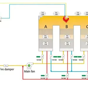
Following secondary desulfurization, the gas stream enters the magnetic energy plume elimination unit, which performs comprehensive deep purification of residual pollutants while simultaneously addressing visible plume formation. An energy conversion and reheating device positioned at the top of the magnetic energy unit elevates the cleaned gas temperature to ensure complete vaporization of residual moisture, preventing condensation upon atmospheric discharge. The final treated gas is discharged through the stack at conditions that guarantee no visible white plume under any meteorological scenario. The system incorporates bypass provisions between the primary and secondary desulfurization towers, enabling online maintenance and inspection without production interruption. The complete process flow is illustrated in the following schematic:

Figure 1: Integrated Process Flow Diagram for Graphitization Flue Gas Treatment System
The system configuration includes two desulfurization absorption towers, one magnetic energy plume elimination unit, one energy conversion device, a complete slurry preparation system, circulation pumps, gypsum dewatering equipment, power supply systems, AICR intelligent control systems, and auxiliary subsystems. This comprehensive infrastructure ensures that all treatment stages operate in coordinated harmony, with the intelligent control system providing real-time optimization of reagent dosing, energy recovery, and emission monitoring. The integrated approach exemplifies the multi-pollutant synergistic control capabilities of advanced regenerative thermal oxidizer (RTO) and related emission control technologies adapted for demanding industrial applications.
3.2 Design Elevation & 3D Layout
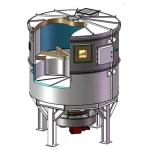
The physical arrangement of treatment equipment was optimized through three-dimensional modeling to ensure efficient spatial utilization, adequate maintenance access, and logical process sequencing. The structural design accommodates the substantial equipment sizes required for handling 140,000 Nm³/h flue gas volumes while maintaining the vertical integration necessary for gravity-assisted slurry flow and gypsum dewatering operations. The elevation design is illustrated in the following 3D rendering:

Figure 2: 3D Design Elevation Drawing of the Integrated Flue Gas Treatment System
The structural configuration features the primary and secondary desulfurization towers positioned in series with the magnetic energy plume elimination unit located downstream. The slurry preparation and gypsum handling facilities are situated at grade level for convenient material access and product removal. The energy conversion devices are strategically positioned to maximize thermal recovery while maintaining the temperature profiles required for optimal downstream treatment performance. All structural components were specified with corrosion-resistant materials and protective coatings suitable for the aggressive chemical environment, with foundation designs accounting for dynamic loads from circulation pumps and seismic requirements for the facility location.
3.3 Process Requirements & Design Considerations
The design of the graphitization flue gas purification system addressed several critical technical requirements specific to this application. The graphitization furnace produces flue gas with extremely high sulfur dioxide concentrations and significant corrosive characteristics, while the gas stream also carries combustible dust particles that necessitate fire and explosion prevention measures. The following design considerations were systematically incorporated:
Fire and Explosion Prevention: The system design incorporates comprehensive fire and explosion prevention measures throughout the treatment train, including explosion relief panels, inert gas purging systems, and temperature monitoring with automatic shutdown provisions. The presence of combustible carbonaceous dust in the flue gas stream necessitates careful management of oxygen concentrations and ignition sources.
Corrosion Resistance: All wetted surfaces in contact with acidic flue gas and slurry are constructed from corrosion-resistant materials including fiberglass-reinforced plastics, acid-resistant alloys, and specialized ceramic linings. The selection of materials was based on detailed corrosion testing under simulated operating conditions to ensure 20-year service life.
Temperature Management: A spray humidification cooling system was installed downstream of the induced draft fans to address elevated gas temperatures that could compromise downstream equipment integrity. Temperature monitoring instruments are installed at the inlets of both primary and secondary desulfurization towers, with real-time feedback to the control system enabling automatic adjustment of equipment operation and process parameters.
Liquid Level Control: All tanks and sumps are equipped with level sensors that provide real-time feedback to the control system, with interlocked valve and pump operation enabling one-button automatic startup functionality. This automation reduces operator workload while preventing overflow and dry-running incidents.
Limestone-Gypsum Process Advantages: The selected limestone-gypsum wet desulfurization process offers several distinct advantages compared to alternative technologies: low energy consumption and operating costs; manageable byproduct handling without secondary pollution; compact footprint with reasonable process layout; optimized system design through advanced computer simulation; low resistance and energy-efficient design through optimized gas velocity; abundant and inexpensive limestone reagent availability; and internal tower agitation and aeration to prevent sedimentation while minimizing investment. These characteristics align with the design principles of modern RTO systems for DeSOx applications, where process efficiency and economic viability are paramount considerations.
3.4 Equipment Selection & Sizing Calculations
Comprehensive equipment sizing calculations were performed to ensure that all system components are appropriately dimensioned for the design operating conditions while providing adequate capacity margins for variable load operation. The following detailed specification tables summarize the key parameters for each major equipment category:
I. Energy Conversion & Cooling Device
| Нет. | Item | Unit | Параметр | Remarks |
|---|---|---|---|---|
| 1 | Flue Gas Volume | m³/h | 85,000 | — |
| 2 | Heat Exchange Area | m² | 934 | — |
| 3 | Equipment Pressure Drop | Pa | 273 | — |
| 4 | Hot Side Inlet Temperature | °C | 170 | — |
| 5 | Hot Side Outlet Temperature | °C | 119.46 | — |
| 6 | Equipment Dimensions | mm×mm×mm | 2,700×4,200×1,200 | — |
II. Induced Draft Fan
| Нет. | Item | Unit | Параметр | Remarks |
|---|---|---|---|---|
| 1 | Single Unit Air Volume | m³/h | 70,000 | — |
| 2 | Wind Pressure | Pa | 6,000 | — |
| 3 | Рабочая температура | °C | 250-300 | — |
| 4 | Single Unit Power | kW | 220 | — |
III. Desulfurization Absorption Tower
| Нет. | Item | Unit | Параметр | Remarks |
|---|---|---|---|---|
| 1 | Flue Gas Volume | m³/h | 140,000 | — |
| 2 | Flue Gas Temperature | °C | 170 | — |
| 3 | SO₂ Inlet Concentration | mg/Nm³ | 11,302 | — |
| 4 | SO₂ Outlet Concentration | mg/Nm³ | 18 | — |
| 5 | Calcium-to-Sulfur Ratio | — | 1.1 | — |
| 6 | Gas Velocity | m/s | < 3 | — |
| 7 | Tower Internal Diameter | m | φ4 | — |
| 8 | Liquid-to-Gas Ratio | — | 23 | — |
| 9 | Spray Layers | Layers | 4 | — |
| 10 | Single Pump Flow Rate | m³/h | 500 | — |
| 11 | Slurry Retention Time | h | 3.5 | — |
| 12 | Limestone Consumption | kg/h | 1,858.632 | Maximum usage |
| 13 | Gypsum Production | kg/h | 2,618.220 | Maximum output |
| 14 | Gypsum Moisture Content | % | 15 | — |
| 15 | Primary Stage Demister | — | 2-Layer Vane Demister | — |
| 16 | Secondary Stage Demister | — | 1-Layer Vane + 1 Tube Bundle Demister | — |
| 17 | Slurry Tank Volume | m³ | 150 | — |
| 18 | Dewatering Cycle | d | 3 | — |
IV. Magnetic Energy Plume Elimination Unit
| Нет. | Item | Unit | Параметр | Remarks |
|---|---|---|---|---|
| 1 | Magnetic Energy Plume Elimination Model | — | BLCNXB-10W | — |
| 2 | Magnetic Energy Plume Elimination Layout | — | Tower External Split Type | — |
| 3 | Magnetic Energy Inlet/Outlet Arrangement | — | Lower Side In, Upper Top Out (Direct) | — |
| 4 | Purification Efficiency | % | ≥ 95 | — |
| 5 | Inlet Mixed Pollutant Concentration | mg/m³ | 100 | — |
| 6 | Outlet Mixed Pollutant Concentration | mg/m³ | 5 | — |
| 7 | Unit Body Resistance | Pa | 300 | — |
| 8 | Treatment Flue Gas Volume | m³/h | 100,000 | — |
| 9 | Flue Gas Temperature | °C | < 40 | — |
| 10 | System Resistance | Pa | 350 | — |
| 11 | Equipment Dimensions | mm×mm | 7,900×7,900 | — |
| 12 | Equipment Height | mm | 17,000 | — |
| 13 | Shell Design Pressure | Pa | ±5,000 | — |
| 14 | Magnetic Energy Generator Model | — | BLEMG-2K | — |
| 15 | Average Power Consumption | kW | 80 | — |
| 16 | Operating Load | т | 195 | — |
V. Energy Conversion & Reheating Device
| Нет. | Item | Unit | Параметр | Remarks |
|---|---|---|---|---|
| 1 | Flue Gas Volume | m³/h | 85,000 | — |
| 2 | Heat Exchange Area | m² | 1,308 | — |
| 3 | Equipment Pressure Drop | Pa | 139 | — |
| 4 | Flue Gas Inlet Temperature | °C | 45 | — |
| 5 | Flue Gas Outlet Temperature | °C | 85 | — |
| 6 | Equipment Dimensions | mm×mm×mm | 3,600×2,300×2,000 | — |
The comprehensive equipment specifications demonstrate the substantial scale of this installation, with the desulfurization absorption tower handling 140,000 m³/h of flue gas containing SO₂ concentrations exceeding 11,000 mg/Nm³. The magnetic energy plume elimination unit, with its 7,900×7,900 mm footprint and 17,000 mm height, represents a significant structural element requiring careful foundation design and seismic consideration. The energy conversion and reheating device provides the critical temperature elevation necessary for plume suppression, raising the cleaned gas from 45°C to 85°C to ensure complete moisture vaporization upon atmospheric discharge. These engineering specifications reflect the demanding requirements of modern NOx gas treatment solutions and multi-pollutant control systems operating at industrial scale.
3.5 As-Built Project Documentation
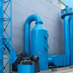
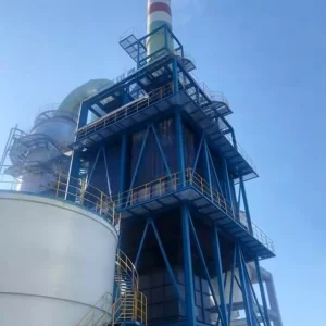
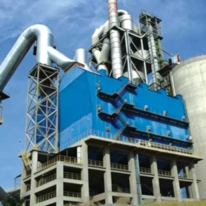
Following completion of construction and commissioning activities, comprehensive as-built documentation was prepared to record the actual installed configuration and verify conformance with design specifications. The as-built drawings provide an accurate record of the completed installation for future maintenance, modification, and regulatory compliance purposes. The following image presents the as-built documentation of the completed project:

Figure 3: As-Built Project Documentation of the Completed Graphitization Flue Gas Treatment Facility
The as-built documentation confirms that all major equipment was installed in accordance with design specifications, with the primary and secondary desulfurization towers, magnetic energy plume elimination unit, and energy conversion devices positioned as shown in the 3D design drawings. The slurry preparation and gypsum handling facilities are fully operational, with the automated control system providing integrated management of all treatment stages. The completed installation demonstrates that large-scale multi-pollutant control systems can be successfully implemented within existing industrial facilities while maintaining production continuity during the construction phase.
4. Operational Performance Analysis
4.1 Energy Consumption Analysis
The energy performance of the integrated treatment system was comprehensively monitored to verify compliance with design efficiency targets and quantify operating cost implications. The system incorporates multiple energy-intensive components including induced draft fans, circulation pumps, oxidation blowers, agitators, and magnetic energy generators. The following detailed energy consumption table presents the installed and actual operating power requirements for each equipment category:
| Нет. | Название оборудования | Single Unit Rated Power (kW) | Total Installed Units | Total Installed Power (kW) | Actual Operating Units | Actual Operating Power (kW) | Operating Status |
|---|---|---|---|---|---|---|---|
| 1 | Main Induced Draft Fan | 200 | 2 | 400 | 2 | 400 | Both units in full operation |
| 2 | Desulfurization Tower Circulation Pump | 75 | 8 | 600 | 8 | 600 | Full operation considered |
| 3 | Slurry Transfer Pump | 7.5 | 2 | 15 | 1 | 7.5 | 1 unit in operation (intermittent) |
| 4 | Oxidation Blower | 75 | 3 | 225 | 2 | 150 | 2 in use, 1 standby |
| 5 | Desulfurization Tower Agitator | 5.5 | 6 | 33 | 6 | 33 | Full operation considered |
| 6 | Fluidized Bed Fan Heater | 20 | 1 | 20 | 1 | 20 | Full operation (actual intermittent) |
| 7 | Star Feeder | 1.1 | 1 | 1.1 | 1 | 1.1 | Full operation (actual intermittent) |
| 8 | Vibrating Motor | 0.55 | 2 | 1.1 | 1 | 0.55 | Full operation considered (actual intermittent) |
| 9 | Screw Conveyor | 2.2 | 1 | 2.2 | 1 | 2.2 | Full operation considered (actual intermittent) |
| 10 | Limestone Slurry Tank Agitator | 5.5 | 1 | 5.5 | 1 | 5.5 | Full operation |
| 11 | Slurry Pump | 4 | 2 | 8 | 1 | 4 | 1 in use, 1 standby (intermittent) |
| 12 | Gypsum Discharge Pump | 22 | 2 | 44 | 1 | 22 | 1 in use, 1 standby (intermittent) |
| 13 | Vacuum Belt Filter | 55.5 | 1 | 55.5 | 1 | 55.5 | Full operation (actual intermittent, 2h operation/1h standby) |
| 14 | Filter Agitator | 5.5 | 1 | 5.5 | 1 | 5.5 | Full operation |
| 15 | Filter Conveyor | 7.5 | 2 | 15 | 1 | 7.5 | 1 in use, 1 standby (intermittent) |
| 16 | Emergency Discharge Pump | 18.5 | 1 | 18.5 | 1 | 18.5 | 1 in use, 1 standby (intermittent) |
| 17 | Emergency Agitator | 22 | 1 | 22 | 1 | 22 | Full operation |
| 18 | Tower Discharge Pump | 3 | 2 | 6 | 1 | 3 | 1 in use, 1 standby (intermittent) |
| 19 | Tower Agitator | 5.5 | 1 | 5.5 | 1 | 5.5 | Full operation |
| 20 | Process Water Pump | 7.5 | 2 | 15 | 1 | 7.5 | 1 in use, 1 standby |
| 21 | Flushing Water Pump | 18.5 | 2 | 37 | 1 | 18.5 | 1 in use, 1 standby (intermittent) |
| 22 | Heat Exchanger Water Pump | 22 | 2 | 44 | 1 | 22 | 1 in use, 1 standby (intermittent) |
| 23 | Magnetic Energy Generator | 80 | 1 | 80 | 1 | 80 | Full operation |
| 24 | Shielded Fan | 11 | 2 | 22 | 2 | 22 | Full operation |
| 25 | Conduction Electric Heater | 2 | 4 | 8 | 4 | 8 | Full operation |
| 26 | Shielded Cabinet Electric Heater | 0.3 | 4 | 1.2 | 4 | 1.2 | Full operation |
| — | TOTAL | — | — | 1,690.1 | — | 1,522.55 | — |
The total installed power capacity of 1,690.1 kW represents the maximum potential electrical demand, while the actual operating power of 1,522.55 kW reflects the optimized operating configuration with standby equipment and intermittent-duty components. The main induced draft fans and desulfurization tower circulation pumps constitute the dominant energy consumers, accounting for approximately 65% of total operating power. The magnetic energy generator, while representing a significant power draw at 80 kW, provides the critical plume elimination function that enables complete visual transparency of stack emissions. The energy analysis confirms that the system operates within design efficiency targets, with the actual operating power representing approximately 90% of installed capacity, indicating appropriate equipment sizing with adequate redundancy for maintenance and reliability.
The project operates at a maximum actual load of 1,522.55 kW with 24-hour daily operation. At an average electricity rate of 0.36 RMB/(kW·h), the daily electricity cost is 13,154.832 RMB, resulting in an annual electricity expense of 4,384,944 RMB based on 8,000 operating hours per year. Water consumption is primarily for flushing, system makeup, and equipment cooling, with a water usage rate of approximately 4.85 t/h. At a water rate of 2 RMB/t, the daily water cost is 240 RMB, yielding an annual water expense of 80,000 RMB at 8,000 operating hours. Limestone consumption is 1,858 t/h at a unit price of 300 RMB/t, generating a daily cost of 13,377.6 RMB and an annual expense of 4,459,200 RMB at 8,000 operating hours. These operating costs are consistent with the economic projections for large-scale wet desulfurization installations and are offset by the value of gypsum byproduct production.
4.2 Compliance Emission Data
Following system commissioning and stabilization, comprehensive emission monitoring was conducted to verify compliance with all design guarantees and regulatory requirements. The monitoring protocol employed continuous emissions monitoring systems (CEMS) for primary parameters supplemented with periodic stack testing for verification. The following detailed compliance data table presents the achieved emission performance across all regulated parameters:
| Нет. | Category | Parameter Name | Value | Unit |
|---|---|---|---|---|
| 1 | Treatment Process | Desulfurization | Limestone-Gypsum Method | — |
| 2 | Denitrification | SNCR Denitrification | — | |
| 3 | Dust Removal | Magnetic Energy Plume Elimination | — | |
| 4 | Plume Elimination | Magnetic Energy Plume Elimination | — | |
| 5 | Стандарты выбросов | Standard Reference | Integrated Emission Standard of Air Pollutants (GB 16297-1996) | — |
| 6 | Nitrogen Oxides | 100 | mg/Nm³ | |
| 7 | Sulfur Dioxide | 18 | mg/Nm³ | |
| 8 | Particulate Matter | 5 | mg/Nm³ | |
| 9 | Carbon Monoxide | 100 | mg/Nm³ | |
| 10 | Hydrogen Fluoride | 5 | mg/Nm³ | |
| 11 | Hydrogen Chloride | 15 | mg/Nm³ | |
| 12 | Plume Elimination | No Visible White Plume | — | — |
| 13 | Treatment Efficiency Analysis | Desulfurization Efficiency | 99.85 | % |
| 14 | Denitrification Efficiency | 50 | % | |
| 15 | Dust Removal Efficiency | 98.4 | % | |
| 16 | Post-Treatment Actual Emission Data | Standard Reference | Integrated Emission Standard of Air Pollutants (GB 16297-1996) | — |
| 17 | Nitrogen Oxides | 48 | mg/Nm³ | |
| 18 | Sulfur Dioxide | 8 | mg/Nm³ | |
| 19 | Particulate Matter | 2.4 | mg/Nm³ | |
| 20 | Carbon Monoxide | 45 | mg/Nm³ | |
| 21 | Hydrogen Fluoride | 1 | mg/Nm³ | |
| 22 | Hydrogen Chloride | 3.5 | mg/Nm³ | |
| 23 | Plume Elimination | No Visible White Plume | — | — |
| 24 | Post-Treatment Efficiency Analysis | Desulfurization Efficiency | 99.93 | % |
| 25 | Denitrification Efficiency | 55 | % | |
| 26 | Dust Removal Efficiency | 99.4 | % |
The operational data demonstrates exceptional achievement of ultra-low emission targets across all measured parameters. The desulfurization efficiency of 99.93% achieved an actual SO₂ outlet concentration of 8 mg/Nm³, substantially below the regulatory limit of 18 mg/Nm³ and representing a remarkable reduction from the inlet concentration of 11,302 mg/Nm³. The particulate matter was reduced to 2.4 mg/Nm³, achieving 99.4% removal efficiency and comfortably meeting the 5 mg/Nm³ standard. The denitrification process achieved 55% efficiency, reducing NOx from 100 mg/Nm³ to 48 mg/Nm³, which is below the regulatory threshold of 50 mg/Nm³. The halogen compounds were effectively controlled, with HF reduced to 1 mg/Nm³ and HCl to 3.5 mg/Nm³, both well within their respective regulatory limits of 5 mg/Nm³ and 15 mg/Nm³. Most significantly, the plume elimination system achieved complete visual transparency with no visible white plume under all observed meteorological conditions, including cold and humid weather that previously produced the most pronounced plume effects.
4.3 Operating Diagram & Control System
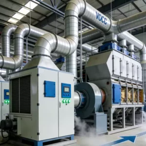
The intelligent control system provides comprehensive monitoring and automated management of all treatment processes through a centralized human-machine interface (HMI). The operating diagram illustrates the real-time status of all major equipment, process parameters, and alarm conditions, enabling operators to maintain optimal system performance with minimal manual intervention. The following image presents the operating diagram of the flue gas treatment system:

Figure 4: Operating Diagram of the Flue Gas Treatment System Control Interface
The control interface displays real-time data for all critical process parameters including flue gas flow rates, temperatures at key locations, SO₂ concentrations at inlet and outlet, slurry pH values, liquid levels in all tanks, and equipment operating status. The system incorporates automatic control loops for reagent dosing, pH adjustment, and energy recovery optimization, with alarm provisions for out-of-range conditions and equipment malfunctions. The AICR intelligent control system enables remote monitoring and diagnostics, facilitating proactive maintenance and minimizing unplanned downtime. This level of automation is characteristic of modern dust collector and emission control systems operating at industrial scale, where consistent performance and regulatory compliance depend on precise process control.
4.4 Operational Risk Analysis
A comprehensive operational risk assessment was conducted to identify potential failure modes and develop mitigation strategies for sustained compliance and system reliability. The primary risks identified include:
Primary Risk 1: Flue Gas Temperature and SO₂ Fluctuation — Variations in graphitization furnace operating conditions can cause significant fluctuations in flue gas temperature and SO₂ concentration, potentially compromising system emission stability. The mitigation strategy involves maintaining close communication between the furnace control room and the flue gas treatment system, with advance notification of operating condition changes to enable proactive adjustment of treatment parameters.
Primary Risk 2: Pipeline Damage and Water Leakage — The aggressive chemical environment and high operating pressures create potential for pipeline corrosion and mechanical damage, leading to water leakage and system downtime. The mitigation strategy involves enhanced personnel patrols and inspection routines, continuous monitoring of equipment condition, ongoing operator training and skill development, and regular revision of safety measures and emergency response plans to ensure effective incident management.
5. Experience Summary & Operational Insights
This project was built upon existing process foundations, fully leveraging wet desulfurization, energy conversion, and magnetic energy plume elimination technologies to achieve ultra-low pollutant emissions in the flue gas. The system continuously monitors and optimizes based on variations in SO₂ concentration and temperature, ultimately achieving the ultra-low emission target with no visible white plume from the stack after operation.
The graphitization Acheson furnace uses raw materials with high sulfur content, resulting in high and uneven SO₂ concentrations in the flue gas. The production cycle is 54 hours, with SO₂ concentrations reaching up to 20,000 mg/Nm³ for 2-3 hours per cycle. The design must ensure desulfurization efficiency under maximum flue gas volume and maximum SO₂ conditions to achieve compliant emission discharge.
5.1 Slurry Preparation System Operating Experience
(1) Ensure that the limestone slurry tank contains sufficient slurry and that the liquid level does not exceed the overflow port. When preparing slurry, add water and limestone simultaneously, controlling the concentration between 15% and 20%.
(2) When the primary desulfurization tower circulation tank pH falls below 4.5, supplement the slurry while ensuring uniform slurry mixing. Maintain the primary desulfurization tower pH between 4.5 and 5.5.
(3) When the secondary desulfurization tower circulation tank pH falls below 5.5, supplement the slurry while ensuring uniform slurry mixing. Maintain the secondary desulfurization tower pH between 5.5 and 6.5.
5.2 Gypsum Dewatering System Operating Experience
(1) Before each gypsum dewatering system pressurized filtration operation, ensure the primary desulfurization tower circulation liquid pH is below 5 and the slurry density exceeds 1.08 g/cm³.
(2) Before starting the gypsum discharge pump, confirm that the inlet and outlet valves are open and power is connected.
(3) Adjust the cyclone overflow valve based on gypsum moisture content, and perform on-site cleanup after each gypsum pressurized filtration cycle.
5.3 Circulation System Operating Experience
(1) When starting circulation pumps, ensure that inlet valves and pump cooling water valves are in the open position.
(2) Test and record the primary and secondary desulfurization tower pH values hourly, observing liquid levels and ensuring they remain within normal ranges.
(3) Flush the demister at specified intervals (4 hours) to ensure normal operation without blockage.
(4) During system operation, ensure the oxidation blower operates normally to guarantee oxidation air flow and gypsum generation.
(5) Control the sump liquid level, and start the drainage pump when the level exceeds the maximum to handle emergency events.
5.4 Magnetic Energy Plume Elimination System Operating Experience
(1) Temperature Adjustment: Control the magnetic energy plume elimination inlet flue gas temperature between 45-55°C, while the energy conversion and reheating device outlet flue gas temperature is controlled above 80°C to ensure normal system operation with no visible white plume.
(2) Voltage Adjustment: The magnetic energy plume elimination magnetic energy generator requires reasonable adjustment, with voltage controlled at approximately 60 kV and maximum current not exceeding 1,000 mA. Simultaneously, monitor the temperature and humidity around the magnetic energy plume elimination device, as well as the electromagnetic tube, magnetic energy generator, and electromagnetic wire components to ensure normal functionality.
(3) Flushing and Cleaning: The magnetic energy plume elimination device requires periodic flushing and cleaning, with cleaning cycles not exceeding 24 hours. Specific timing should be determined based on actual operating conditions and emission standards.
6. Conclusions & Industry Implications
This case study demonstrates that integrated wet desulfurization, energy conversion, and magnetic energy plume elimination technologies can reliably achieve ultra-low emission standards for graphitization furnace operations while simultaneously eliminating visible plume formation. The key technical insights from this implementation include the critical importance of two-stage desulfurization for handling extreme SO₂ concentrations exceeding 11,000 mg/Nm³, the effectiveness of magnetic energy technology for deep pollutant purification and plume suppression, and the substantial energy recovery benefits provided by integrated heat exchange systems.
For facilities contemplating similar emission control upgrades, several recommendations emerge from this experience. First, comprehensive characterization of flue gas variability, including peak SO₂ concentrations and production cycle effects, is essential for appropriate equipment sizing and buffer capacity design. Second, the two-stage desulfurization approach with bypass provisions provides both operational flexibility and maintenance accessibility that single-stage configurations cannot match. Third, magnetic energy plume elimination technology offers a unique combination of deep pollutant removal and visual emission control that addresses both regulatory compliance and community relations objectives. Finally, the intelligent control system with real-time monitoring and automated optimization is essential for maintaining consistent performance under variable operating conditions.
As the lithium-ion battery industry continues its exponential growth trajectory and environmental regulations tighten globally, the technologies and design approaches validated in this project will become increasingly relevant across the graphitization and carbon processing sectors. The successful integration of wet desulfurization, energy recovery, and magnetic energy plume elimination within a single, optimized treatment train provides a replicable model for facilities facing similar extreme pollutant challenges. The demonstrated performance confirms that advanced регенеративный термический окислитель and related multi-pollutant control technologies represent mature, reliable solutions capable of meeting the most stringent contemporary emission requirements while delivering the operational flexibility necessary for batch-process industrial applications.
About This Analysis: This technical case study was prepared from an industrial emission control specialist perspective, examining real-world performance data from a major graphitization facility multi-pollutant control installation. The analysis reflects current best practices in wet desulfurization technology, magnetic energy plume elimination, and integrated emission control engineering, intended to inform facility managers, environmental engineers, and regulatory stakeholders considering similar emission control investments. For additional information on advanced thermal oxidation and emission control technologies, explore our comprehensive resources on regenerative thermal oxidizer systems and related NOx treatment solutions.