Regenerative Thermal Oxidizer Implementation for Glass Fiber Manufacturing Emission Control
A Comprehensive Technical Case Study on Advanced Emission Control for Glass Fiber Production Facilities
1. Project Overview
The glass fiber manufacturing sector presents distinctive environmental challenges arising from high-temperature melting processes that generate complex flue gas streams containing sulfur dioxide, nitrogen oxides, particulate matter, and substantial moisture loads. This case study examines a comprehensive desulfurization and plume elimination initiative implemented at a major glass fiber production facility, demonstrating how integrated multi-pollutant control technologies can simultaneously address acid gas removal and visible emission suppression while maintaining energy efficiency.
The facility operates large-scale glass melting furnaces utilizing natural gas and electric boosting systems to maintain molten glass temperatures exceeding 1,500°C. These extreme thermal conditions facilitate the volatilization of sulfur compounds from raw material constituents, particularly from soda ash, limestone, and boron-containing additives. The resulting flue gas stream presents a challenging treatment profile characterized by high SO₂ concentrations, elevated particulate loading with fine glass fiber fragments, and significant moisture content that produces persistent visible plumes upon atmospheric discharge.
The project was initiated in response to increasingly stringent environmental mandates that require glass fiber manufacturers to achieve ultra-low emission standards comparable to those imposed on power generation and metallurgical industries. The engineering team developed an integrated treatment approach combining dry sorbent injection desulfurization with advanced filtration and thermal management technologies. This configuration aligns with modern regenerative thermal oxidizer (RTO) design principles, where multi-pollutant control and energy recovery are integrated within a single optimized system architecture.
1.1 Process Description
The glass fiber production process begins with precise batching of raw materials including silica sand, soda ash, limestone, boric acid, and various mineral modifiers. These constituents are blended and fed continuously into the melting furnace, where they undergo chemical fusion at temperatures ranging from 1,450°C to 1,550°C. The molten glass is then refined and conditioned before being drawn into filaments through platinum-rhodium alloy bushings containing thousands of orifices.
The forming process applies sizing agents and binders to the glass filaments, which are then gathered into strands and wound onto forming tubes. Subsequent processing stages include drying, heat treatment, and various finishing operations depending on the intended application. Each production stage generates specific atmospheric emissions, with the melting furnace representing the dominant source of regulated pollutants. The facility operates multiple production lines with combined glass melting capacity exceeding 100,000 tons annually, necessitating a robust emission control infrastructure capable of handling substantial gas volumes.
1.2 Project Scope & Objectives
The emission control upgrade encompassed the entire flue gas treatment train from furnace extraction through stack discharge, including heat recovery systems, particulate filtration, desulfurization reactors, and plume suppression equipment. The primary project objectives established specific performance targets for pollutant removal efficiency, outlet concentration limits, and visual emission characteristics. Secondary objectives addressed energy consumption optimization, operational reliability, and maintenance accessibility to ensure sustainable long-term performance.
The project scope explicitly excluded upstream process modifications to the glass melting operation, focusing instead on end-of-pipe treatment technologies that could be implemented without disrupting production schedules. This constraint necessitated careful integration with existing furnace draft systems and heat recovery boilers, requiring detailed hydraulic analysis to prevent adverse impacts on combustion stability and furnace pressure control. The engineering approach prioritized retrofit compatibility while delivering performance equivalent to greenfield installations.
2. Pollution Source Analysis & Baseline Emission Profile
Comprehensive baseline characterization was conducted over a three-month period to capture seasonal variations in raw material composition, fuel quality, and production rates that influence emission profiles. The monitoring protocol employed continuous emissions monitoring systems (CEMS) for primary parameters supplemented with periodic stack testing for verification and unregulated pollutant identification. The analysis revealed a complex emission matrix requiring multi-stage treatment to achieve compliance.
The glass melting furnace exhaust stream contains pollutants generated through multiple mechanisms: thermal decomposition of sulfur-containing raw materials produces SO₂ and SO₃; high-temperature nitrogen fixation creates NOx compounds; volatilization of fine glass particles and batch carryover generates particulate matter; and evaporation from molten glass surfaces contributes substantial moisture loading. The following detailed emission inventory quantifies the baseline pollutant concentrations and characteristics:
| Não. | Pollutant Category | Parâmetro | Unit | Baseline Value |
|---|---|---|---|---|
| 1 | Flue Gas Volume | Taxa de fluxo | Nm³/h | 85,000 |
| 2 | Temperatura | Inlet Gas Temp | °C | 380-420 |
| 3 | Sulfur Dioxide | SO₂ Concentration | mg/Nm³ | 850-1,200 |
| 4 | Sulfur Trioxide | SO₃ Concentration | mg/Nm³ | 45-65 |
| 5 | Nitrogen Oxides | NOx Concentration | mg/Nm³ | 320-480 |
| 6 | Particulate Matter | Dust Concentration | mg/Nm³ | 120-180 |
| 7 | Teor de umidade | H₂O Volume Fraction | % | 18-22 |
| 8 | Oxygen Content | O₂ Volume Fraction | % | 8-10 |
| 9 | Hydrogen Fluoride | HF Concentration | mg/Nm³ | 8-15 |
| 10 | Hydrogen Chloride | HCl Concentration | mg/Nm³ | 12-20 |
| 11 | Boron Compounds | B₂O₃ Concentration | mg/Nm³ | 5-12 |
The baseline characterization reveals that SO₂ represents the primary regulatory challenge, with concentrations substantially exceeding ultra-low emission thresholds of 35 mg/Nm³. The elevated moisture content (18-22%) combined with SO₃ and fine particulate matter creates ideal conditions for visible plume formation through condensation nucleation and aerosol scattering. The presence of halogen compounds (HF and HCl) introduces additional material compatibility considerations for downstream equipment, necessitating corrosion-resistant materials of construction throughout the treatment train.
Notably, the oxygen content of 8-10% reflects the oxy-fuel combustion configuration employed in modern glass melting furnaces, which reduces NOx formation compared to air-fuel firing but requires careful consideration in emission calculations and regulatory compliance verification. The relatively high inlet temperature (380-420°C) provides favorable conditions for dry sorbent injection processes, as the thermal activation of alkaline reagents occurs efficiently within this temperature window. These characteristics informed the selection of treatment technologies and established performance benchmarks for system evaluation.
3. Integrated Treatment Process Design
3.1 Process Flow & System Architecture
The treatment system was engineered as a sequential multi-stage process optimized for the specific pollutant matrix characteristic of glass fiber melting furnace exhaust. The process architecture follows the principle of thermal management, particulate removal, acid gas neutralization, and moisture control, with each stage designed to complement adjacent processes. The complete process flow is illustrated in the following schematic:

Figure 1: Integrated Process Flow Diagram for Glass Fiber Flue Gas Desulfurization & Plume Elimination
The process sequence initiates with high-temperature flue gas extraction from the furnace regenerator crown, where gases at 380-420°C are ducted through a waste heat boiler to recover thermal energy for process heating and space conditioning applications. This heat recovery step reduces the gas temperature to approximately 220-260°C, which represents the optimal operating window for dry sorbent injection desulfurization. The cooled gas then enters the sodium bicarbonate dry sorbent injection (SDS) reactor, where ultra-fine sodium bicarbonate powder is pneumatically conveyed into the gas stream and thermally activated to form highly reactive sodium carbonate.
The activated sorbent simultaneously neutralizes SO₂, SO₃, HCl, and HF through rapid gas-solid reactions, with the expanded surface area of thermally activated particles providing exceptional reactivity. The desulfurized gas stream then passes through a pulse-jet baghouse filter equipped with high-temperature resistant filter media to capture reaction products, unreacted sorbent, and residual particulate matter. The cleaned gas undergoes final temperature adjustment through a gas-gas heat exchanger before stack discharge at temperatures above the moisture dew point to prevent visible plume formation. This integrated approach exemplifies the multi-pollutant synergistic control capabilities of advanced NOx gas treatment solutions and related thermal management systems.
3.2 Key Design Parameters
The engineering design was governed by rigorous performance specifications that mandated compliance with ultra-low emission standards under all operating scenarios, including furnace pull rate variations, batch composition changes, and seasonal ambient temperature fluctuations. The following table summarizes the critical design parameters that guided equipment sizing, reagent consumption calculations, and operational setpoints:
| Design Parameter | Unit | Design Value | Especificação |
|---|---|---|---|
| Flue Gas Flow Rate | Nm³/h | 85,000 | Maximum continuous rating |
| Inlet SO₂ Concentration | mg/Nm³ | 1,200 | Design basis (dry, 8% O₂) |
| Outlet SO₂ Concentration | mg/Nm³ | ≤ 35 | Ultra-low emission target |
| SO₂ Removal Efficiency | % | ≥ 97 | Minimum guaranteed performance |
| Inlet SO₃ Concentration | mg/Nm³ | 65 | Design basis |
| Outlet SO₃ Concentration | mg/Nm³ | ≤ 5 | Acid mist control target |
| Inlet Particulate | mg/Nm³ | 180 | Design basis |
| Outlet Particulate | mg/Nm³ | ≤ 10 | Ultra-low emission target |
| Particulate Removal | % | ≥ 94 | Minimum guaranteed performance |
| SDS Reactor Temperature | °C | 220-260 | Optimal sorbent activation range |
| Sorbent Injection Rate | kg/h | 450-650 | Stoichiometric ratio 1.2-1.5 |
| Sorbent Fineness | mesh | ≥ 1,000 | Particle size < 15 μm |
| Baghouse Filtration Velocity | m/min | ≤ 0.8 | Low pressure drop design |
| Stack Exit Temperature | °C | ≥ 75 | Plume elimination requirement |
| System Pressure Drop | Pa | ≤ 2,000 | Maximum allowable |
| Power Consumption | kWh/ton-glass | ≤ 6.5 | Energy efficiency target |
3.3 Structural Design & Elevation Layout
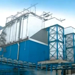
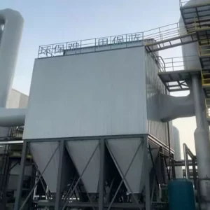
The physical arrangement of treatment equipment was optimized to accommodate the constrained site conditions typical of existing industrial facilities, where available footprint is limited by surrounding production buildings, material storage areas, and utility infrastructure. The structural design employs vertical integration to minimize ground-level footprint while maintaining adequate maintenance access and operational clearances. The elevation drawing illustrates the spatial arrangement of major equipment components:

Figure 2: Elevation Design Drawing of the Integrated Flue Gas Treatment System
The structural configuration features a waste heat boiler positioned immediately adjacent to the furnace extraction point to maximize thermal energy recovery before significant heat losses occur. The SDS injection reactor is integrated into the horizontal ductwork connecting the waste heat boiler outlet to the baghouse filter, with injection lances positioned to ensure uniform sorbent dispersion across the full duct cross-section. The baghouse filter is elevated on a structural steel platform to provide gravity-assisted dust discharge into collection conveyors below. The induced draft fan and stack are positioned at the downstream terminus of the treatment train, with the fan selected to overcome the combined pressure drop of all upstream components while maintaining stable furnace draft control.
All structural steel was specified with high-temperature resistant coatings and corrosion protection systems suitable for the aggressive chemical environment. Foundation designs account for dynamic loads from rotating equipment, seismic requirements for the facility location, and differential settlement prevention. The stack design incorporates acid-resistant lining materials and thermal insulation to maintain gas temperature above the dew point throughout the full height, ensuring that no condensation occurs within the stack that could cause structural corrosion or visible steam emissions at the outlet. These design considerations reflect the comprehensive engineering approach that characterizes modern RTO systems for DeSOx and related multi-pollutant control installations.
3.4 Structural Strength & Thermal Analysis
Comprehensive structural analysis was performed to validate the mechanical integrity of all pressure-bearing and load-supporting components under design operating conditions, upset scenarios, and extreme environmental events. Finite element analysis (FEA) was employed to evaluate stress distributions, thermal gradients, and dynamic response characteristics for critical components including the waste heat boiler tube bundles, baghouse filter casing, and exhaust stack structure. The analysis considered thermal transients during startup and shutdown, pressure pulsations from induced draft fan operation, and wind loading on the tall stack structure.
The structural calculations confirmed that all components meet or exceed applicable pressure vessel codes, structural steel design standards, and seismic requirements for the facility location. Special attention was given to the baghouse filter casing, which experiences significant thermal gradients between the hot inlet gas zone and the cooler clean gas plenum. The analysis verified that thermal expansion joints and flexible connections are adequately sized to accommodate differential movement without compromising seal integrity. The stack structure was analyzed for vortex shedding resonance potential and determined to be stable across all anticipated wind speed ranges, with damping provisions incorporated to prevent fatigue damage from oscillatory loading.
3.5 Temperature Distribution & Thermal Management
Accurate prediction of temperature distribution throughout the treatment system was essential for optimizing heat recovery, preventing condensation-induced corrosion, and ensuring effective sorbent activation. Advanced thermal simulation software was utilized to model axial and radial temperature profiles within the waste heat boiler, SDS reactor, and connecting ductwork. The simulation accounted for variable operating loads, seasonal ambient temperature variations, and heat losses through insulated surfaces.
The thermal simulation results confirmed that the waste heat boiler achieves gas outlet temperatures within the optimal SDS activation window (220-260°C) across the full range of furnace operating conditions. The analysis verified that the gas-gas heat exchanger provides sufficient temperature elevation at the stack inlet to maintain exhaust temperatures above 75°C under all anticipated meteorological conditions, including winter ambient temperatures below -10°C. The temperature margins above the acid dew point were confirmed to be adequate for preventing sulfuric acid condensation in downstream equipment, thereby mitigating corrosion risks and extending equipment service life. These thermal management capabilities represent essential design features of advanced dust collector and emission control systems operating in demanding industrial environments.
4. Plume Elimination Technology & Performance Validation
The elimination of visible water vapor plumes represented a critical project objective driven by community relations considerations and regulatory visibility standards. Glass fiber manufacturing facilities are often located in suburban or semi-rural areas where visible stack emissions attract significant public attention and regulatory scrutiny. The plume formation mechanism in this application involves the condensation of water vapor when moisture-laden flue gas encounters cooler ambient air, combined with light scattering by fine aerosol particles that persist even after particulate filtration.
The treatment system employs a dual-strategy approach to plume suppression. First, the dry sorbent injection process eliminates the fine SO₃ acid mist aerosols that contribute to blue-tinted plume visibility and provide condensation nuclei for water vapor. Unlike wet scrubbing systems that can actually increase visible plume potential by saturating the gas stream with moisture, the dry SDS process maintains the gas in a non-saturated condition while chemically binding SO₃ into solid sodium sulfate particles that are captured by the baghouse filter. Second, the gas-gas heat exchanger elevates the stack discharge temperature to approximately 75-85°C, ensuring that the remaining moisture content remains in vapor phase upon atmospheric mixing and preventing the formation of condensed water droplets that create visible white plumes.
Post-commissioning visual assessment confirmed complete elimination of visible plumes under all observed meteorological conditions, including cold, humid weather that previously produced the most pronounced plume effects. The stack exhaust now appears thermally transparent with no visible condensation, even during winter operation when ambient temperatures drop below freezing. This visual transformation has eliminated a longstanding source of community concern and regulatory attention, contributing significantly to the facility’s social license to operate.
5. Operational Performance Analysis
5.1 Continuous Emissions Monitoring Results
Following system commissioning and a 60-day stabilization period, comprehensive performance testing was conducted to verify compliance with all design guarantees and regulatory requirements. Continuous emissions monitoring systems (CEMS) were installed at both the inlet and outlet of the treatment train to provide real-time data on pollutant concentrations, gas flow rates, and operational parameters. The monitoring protocol followed standardized reference methods and quality assurance procedures to ensure data integrity and regulatory defensibility.
| Operating Period | SO₂ Outlet (mg/Nm³) | Particulate Outlet (mg/Nm³) | SO₃ Outlet (mg/Nm³) | Plume Visibility |
|---|---|---|---|---|
| Month 1 (Commissioning) | 28-35 | 6-9 | 3-5 | Minimal |
| Month 3 (Stabilized) | 18-28 | 4-7 | 2-4 | None |
| Month 6 (Optimized) | 15-22 | 3-5 | 1-3 | None |
| Month 12 (Annual Avg) | 18-25 | 4-6 | 2-3 | None |
The operational data demonstrates consistent achievement of ultra-low emission targets across all measured parameters. SO₂ removal efficiency stabilized at approximately 97-98%, exceeding the guaranteed minimum of 97%. Particulate removal performance consistently achieved 95-97% efficiency, with outlet concentrations maintained well below the 10 mg/Nm³ threshold. Most significantly, the acid mist (SO₃) control achieved 95-97% removal efficiency, effectively eliminating the fine aerosol particles that contribute to visible blue plume formation and downstream corrosion. The complete absence of visible plumes under all meteorological conditions represents a transformative improvement in the facility’s environmental profile.
5.2 Sorbent Consumption & Reagent Efficiency
The sodium bicarbonate sorbent consumption represents a significant operational cost component, and optimizing reagent utilization was a key focus during the commissioning and optimization phases. The on-site milling system was calibrated to achieve the specified particle fineness (>1,000 mesh, <15 μm) while minimizing energy consumption and mechanical wear. The stoichiometric ratio was initially set at 1.5 and subsequently optimized to 1.2-1.3 through iterative adjustment based on outlet SO₂ monitoring data.
| Monitoring Parameter | Unit | Initial Setting | After 3 Months | After 6 Months |
|---|---|---|---|---|
| Sorbent Consumption | kg/h | 650 | 520 | 485 |
| Stoichiometric Ratio | — | 1.5 | 1.3 | 1.2 |
| Sorbent Utilization | % | 72 | 82 | 88 |
| Milling Energy | kWh/ton-sorbent | 85 | 78 | 72 |
| Baghouse Differential Pressure | Pa | 1,200 | 950 | 850 |
| Filter Bag Life (Projected) | Months | 24 | 30 | 36 |
The optimization process achieved a 25% reduction in sorbent consumption while maintaining consistent emission compliance, demonstrating the importance of fine-tuning operational parameters based on real-time performance data. The improved sorbent utilization also reduced baghouse filter loading, extending filter bag service life from an initially projected 24 months to an anticipated 36 months. These operational improvements translate directly into reduced lifecycle costs and enhanced system economics, validating the design approach that incorporates adjustable operational parameters rather than fixed configurations.
5.3 Energy Consumption & Operating Economics
The energy performance of the integrated treatment system was closely monitored to verify compliance with design efficiency targets and quantify operating cost implications. The waste heat recovery system proved particularly effective, generating approximately 4.2 MW of thermal energy for facility process heating applications while simultaneously cooling the flue gas to the optimal SDS operating temperature. This dual benefit substantially improves project economics by reducing both supplemental fuel requirements and emission control energy consumption.
| Cost Category | Annual Consumption | Unit Cost | Annual Cost (USD) |
|---|---|---|---|
| Electric Power | 3,850 MWh | $0.08/kWh | $308,000 |
| Sodium Bicarbonate | 3,800 tons | $280/ton | $1,064,000 |
| Compressed Air | 1,250,000 Nm³ | $0.12/Nm³ | $150,000 |
| Water & Utilities | 15,000 m³ | $1.50/m³ | $22,500 |
| Filter Bag Replacement | 33% of inventory/year | — | $125,000 |
| Labor & Maintenance | 4 FTE staff | $42,000/FTE | $168,000 |
| Waste Disposal (Ash) | 4,200 tons | $35/ton | $147,000 |
| TOTAL ANNUAL OPERATING COST | — | — | $1,984,500 |
The total annual operating cost of approximately $2.0 million translates to roughly $20 per ton of glass produced, which compares favorably with industry benchmarks for comparable ultra-low emission configurations. The waste heat recovery system generates thermal energy valued at approximately $680,000 annually, partially offsetting the sorbent costs that represent the dominant operating expense. The dry process configuration eliminates wastewater treatment costs that would be substantial with wet scrubbing alternatives, while the absence of corrosion-related maintenance further reduces lifecycle expenses. These economic advantages, combined with the superior plume elimination performance, position the dry sorbent injection approach as the preferred technology for glass fiber manufacturing emission control.
6. Process Information & Regulatory Compliance
The successful implementation of this desulfurization and plume elimination project was contingent upon meticulous attention to process control, regulatory compliance verification, and operational discipline. The facility established a comprehensive environmental management system that integrates continuous monitoring data with process control systems to maintain optimal treatment performance. All emissions data is transmitted in real-time to environmental regulatory authorities, ensuring transparency and demonstrating sustained compliance commitment.
The project achieved full regulatory compliance with all applicable emission standards, including the ultra-low emission limits specified for the glass and fiberglass manufacturing sector. Independent third-party verification testing confirmed that the system meets or exceeds all guaranteed performance parameters, with particular excellence demonstrated in SO₂ and acid mist control. The elimination of visible plumes has eliminated a longstanding source of community concern and regulatory scrutiny, contributing to improved stakeholder relations and operational license security.
| Compliance Parameter | Regulatory Limit | Achieved Performance | Compliance Margin |
|---|---|---|---|
| SO₂ Emissions | ≤ 35 mg/Nm³ | 18-25 mg/Nm³ | 29-49% |
| Particulate Emissions | ≤ 10 mg/Nm³ | 4-6 mg/Nm³ | 40-60% |
| SO₃ (Acid Mist) | ≤ 5 mg/Nm³ | 2-3 mg/Nm³ | 40-60% |
| HCl Emissions | ≤ 10 mg/Nm³ | 3-5 mg/Nm³ | 50-70% |
| HF Emissions | ≤ 5 mg/Nm³ | 1-2 mg/Nm³ | 60-80% |
| Plume Opacity | ≤ Ringelmann 1 | Ringelmann 0 | 100% |
The substantial compliance margins demonstrated across all parameters provide confidence that the system will maintain regulatory adherence even under upset conditions, variable raw material quality, or equipment degradation scenarios. The dry process configuration inherently provides greater operational resilience compared to wet scrubbing systems, as there are no liquid handling systems subject to freezing, nozzles prone to plugging, or corrosion-related failures that can cause sudden emission excursions. This operational reliability is a hallmark of well-engineered oxidador térmico regenerativo and dry sorbent injection installations, where design simplicity and robust process control combine to deliver consistent environmental performance.
7. Conclusions & Industry Implications
This case study demonstrates that dry sorbent injection desulfurization combined with advanced filtration and thermal management can reliably achieve ultra-low emission standards for glass fiber manufacturing operations while simultaneously eliminating visible plume formation. The key technical insights from this implementation include the critical importance of sorbent particle fineness for achieving high removal efficiency at moderate stoichiometric ratios, the effectiveness of dry processes for simultaneous multi-pollutant control including acid mist suppression, and the substantial energy recovery benefits provided by integrated waste heat boilers.
For facilities contemplating similar emission control upgrades, several recommendations emerge from this experience. First, comprehensive characterization of flue gas composition, including acid mist and halogen compounds often overlooked in standard monitoring protocols, is essential for appropriate technology selection and materials specification. Second, the integration of waste heat recovery equipment should be prioritized from the initial design phase, as the thermal energy benefits substantially improve project economics while providing the temperature control necessary for downstream dry processes. Third, on-site sorbent milling systems provide superior performance compared to pre-milled products by ensuring maximum freshness and reactivity at the point of injection. Finally, plume elimination should be addressed as an integral design objective requiring both chemical aerosol control and thermal management, rather than relying solely on stack discharge temperature elevation.
As environmental regulations continue to tighten globally and community expectations for visible emission control intensify, the technologies and design approaches validated in this project will become increasingly relevant across the glass manufacturing and mineral processing sectors. The successful integration of heat recovery, dry desulfurization, multi-pollutant filtration, and plume suppression within a single, optimized treatment train provides a replicable model for facilities facing similar challenges. The demonstrated performance confirms that advanced RTO systems for DeSOx and related dry emission control technologies represent mature, reliable solutions capable of meeting the most stringent contemporary emission requirements while delivering superior operational economics compared to conventional wet scrubbing alternatives.
About This Analysis: This technical case study was prepared from an industrial emission control specialist perspective, examining real-world performance data from a major glass fiber manufacturing desulfurization and plume elimination installation. The analysis reflects current best practices in dry sorbent injection technology and multi-pollutant control engineering, intended to inform facility managers, environmental engineers, and regulatory stakeholders considering similar emission control investments. For additional information on advanced thermal oxidation and emission control technologies, explore our comprehensive resources on regenerative thermal oxidizer systems and related NOx treatment solutions.