
Separate finishing vapors from the dust and residues that travel with them
Furniture finishing and wood-coating plants can produce a mixed exhaust profile. Spray application may release solvent vapor and droplets, drying can change gas temperature and composition, while sanding or handling operations can generate particles. These sources should be mapped separately before a plant assumes that one RCO arrangement can treat the combined stream. The map should identify each hood, branch, fan, filter, dryer, and point where streams meet.
A common mistake is to describe the whole exhaust as either dusty or solvent-rich. Those labels hide the physical differences that determine pretreatment. Dry sanding dust, sticky coating mist, condensable organic vapor, and gas-phase solvent are not interchangeable contaminants. Record which are present, how they vary by production stage, and whether sampling supports the description. This makes it possible to match each proposed upstream device to a clear removal objective. RCO catalyst compatibility review provides a related technical reference for this decision.
Map the finishing process and its contaminant routes
Begin with a process inventory. List coating types, thinners where used, cleaners, drying conditions, and the schedule for color or material changes. Use current safety data and formulation records to identify known organic compounds. Total VOC concentration alone does not establish catalyst compatibility, especially if a small fraction of the stream contains a constituent that has not been reviewed. Mark unknowns explicitly rather than assuming the average concentration makes them unimportant.
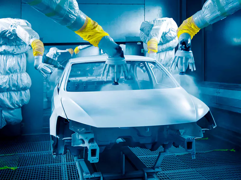
Sanding and finishing may be connected operationally but should not automatically share a treatment design basis. Dust-rich extraction can have different flow and particulate loading from spray-booth or oven exhaust. If those streams are mixed, the resulting gas may carry material into equipment that was not designed for it. Review routing and existing separation before deciding whether source segregation or additional pretreatment is needed.
Coating mist can behave differently from dry dust. Droplets may contain resin, pigment, or other coating constituents that leave deposits if they reach cooler surfaces. A device intended for dry particulate does not necessarily capture fine liquid aerosol effectively. The plant should identify physical form, loading pattern, and cleaning requirements, then request evidence that the proposed separator suits the actual material and flow range.
Drying equipment changes the gas profile as temperature and solvent release change over time. A warm steady-state sample may not represent cold startup, a slow production run, or the period after a coating recipe changes. Record temperature and flow together with operating state. If condensation may occur in ducts or equipment during cooldown, examine likely low points, drains, and colder sections rather than assuming the source temperature remains constant all the way to the oxidizer.
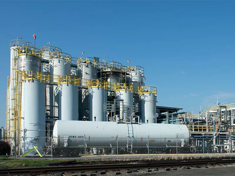
Catalyst compatibility requires a chemistry-specific review. Different coating formulations and cleaning agents can contain constituents with different effects on catalytic activity. The impact depends on chemical form, concentration, temperature, and catalyst selection. Ask the supplier which compounds and exposure ranges have been evaluated and what additional sampling is recommended. Do not turn a general contaminant list into an unsupported claim that a particular product or process is unsuitable.
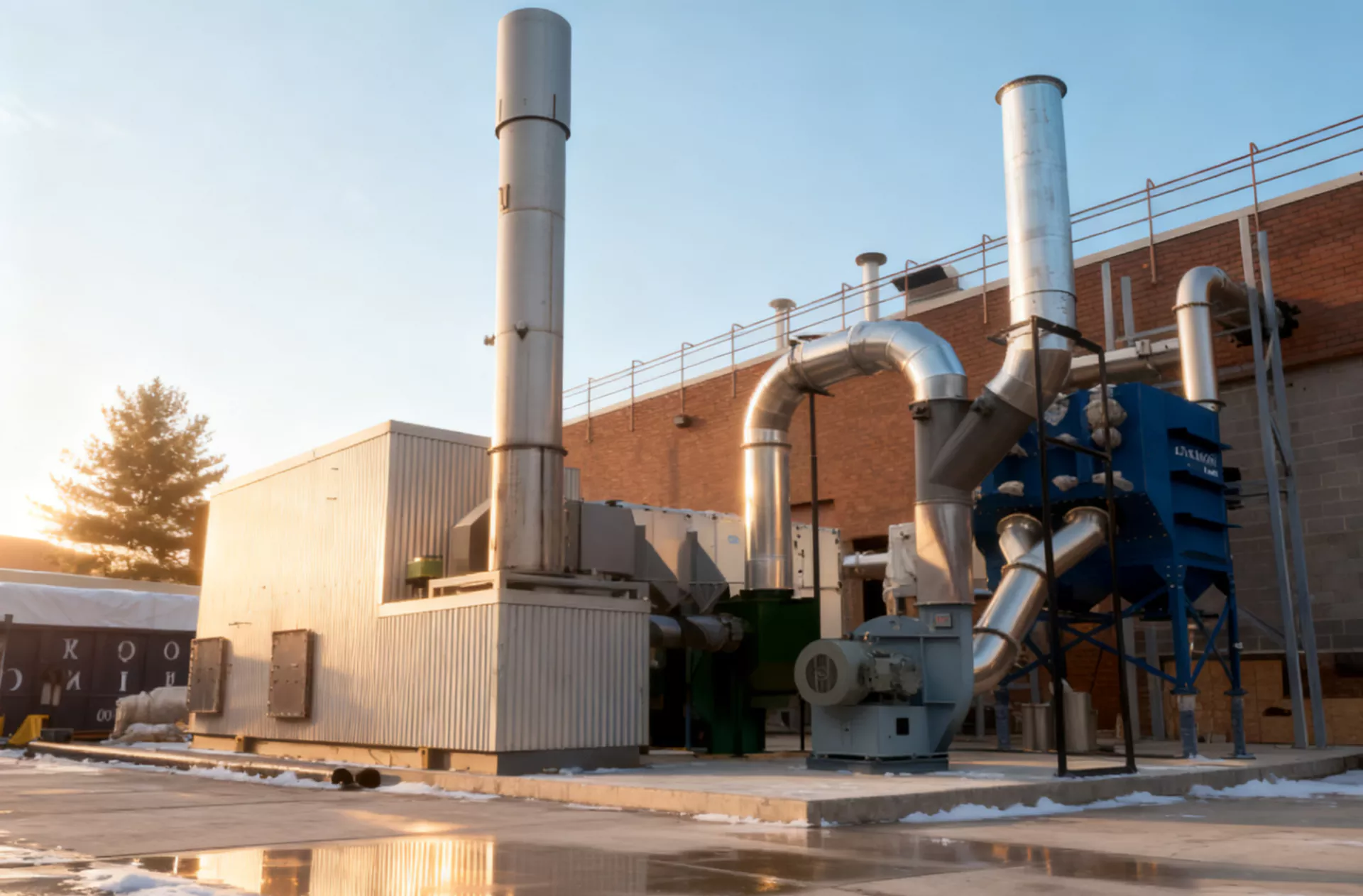
Pretreatment should be specified by function. Particle removal, mist separation, condensate management, and protection from a known chemical constituent are separate design questions. Each component needs an expected operating range, a monitoring point, a maintenance method, and a response to failure. If the supplier proposes a filter or separator, ask what it is expected to remove and how the plant can tell when service is required.
Select pretreatment and catalyst requirements from measured evidence
Flow data should cover different production modes. Several finishing booths may operate together, while sanding or cleaning extraction can run on a different schedule. Record branch flows, combined header flow, and fan operating point under representative conditions. Do not size a system from the sum of nameplate airflow values without considering how sources actually operate together. The simultaneous duty is what the installed system must handle.
Pressure drop provides useful evidence only when measurement points and operating conditions are known. Filters, separators, ducts, regenerative media, catalyst channels, dampers, and stack all contribute resistance. If pressure rises, compare flow and fan state, then inspect the relevant section under approved isolation procedures. A high reading does not automatically prove catalyst plugging; the cause may be an upstream filter, a duct deposit, or an instrument issue. For related design context, see pressure-drop troubleshooting.
| Source or contaminant | What to characterize | Design consequence |
|---|---|---|
| Spray booth | Coating chemistry, aerosol form, branch flow | Mist separation and source capture |
| Sanding extraction | Particle loading and operating schedule | Separate dust control and pressure-drop management |
| Dryer or oven | Temperature, solvent release, startup and idle modes | Heat balance and representative testing |
| Cleaning stage | Agents, timing, concentration variability | Catalyst compatibility and change control |
| Combined header | Simultaneous airflow and fan data | Installed system duty and balancing |
Material changes should trigger a review before the new formulation becomes routine. A new coating, thinner, cleaner, or curing schedule can change both gas-phase chemistry and physical deposits. Compare the proposed change with the original operating envelope and determine whether sampling or supplier consultation is needed. Keep the review proportionate to the change, but do not let a production trial quietly become a permanent condition the catalyst specification never considered.
Safety controls should be designed for the actual process and equipment. Relevant signals depend on the approved hazard review and may include flow, fan status, temperature, valve position, or other permissives. Operators need a defined response to loss of exhaust, abnormal conditions, or an instrument fault. Never improvise a bypass or reduce ventilation without the required engineering and safety authorization.
The energy estimate should distinguish the drying process from the oxidizer’s own heat balance. Inlet temperature, VOC loading, airflow, starts and stops, and regenerative heat recovery affect supplemental energy. Ask suppliers to state which operating cases their estimate includes. If the finishing line runs in short batches with frequent idle periods, that schedule should be visible in the estimate rather than hidden behind an annual-hours assumption.
A practical review sequence
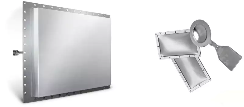
Maintenance access should be considered while the layout is being developed. Filters and mist separators need safe service access; catalyst modules may require handling space and a documented removal path; pressure taps and instruments must be reachable for inspection. A plant can fit the vessel into a corner and still make routine work unnecessarily difficult. Involve maintenance staff early and define isolation, lifting, and waste-handling requirements.
A supplier comparison should use a shared scope matrix. Confirm whether duct modifications, pretreatment, fan changes, platforms, utilities, controls integration, sampling ports, spares, training, and commissioning are included. Ask for exclusions in writing. A low equipment price is not directly comparable with a proposal that includes the work needed to connect and maintain the system safely.
Acceptance testing should represent the process states the RCO is expected to handle. Define the relevant coating family, line rate, flow, temperature, sampling method, and emissions target before the test. If one sample cannot represent a materially different cleaning or drying mode, state how that mode will be evaluated. Keep performance acceptance separate from protective-function tests; one does not replace the other.
After commissioning, retain a baseline for flow, pressure, temperature, process mode, alarms, and maintenance events. Use the same measurement points where possible when comparing later readings. This makes it easier to determine whether a change follows a new coating, a loaded separator, or a mechanical problem. Store enough context that another shift can interpret the record without guessing which product was running.
A practical change-control register should list new coating materials, cleaning agents, airflow changes, new extraction branches, and alterations to drying temperature or schedule. For each change, note who reviewed it, what evidence was used, and whether follow-up sampling is required. That record helps preserve the relationship between the approved exhaust envelope and the process actually running on the floor. Before freezing the scope, review preparing process information for an RCO proposal with the team responsible for the operating envelope.
Често задавани въпроси
Can sanding dust and coating VOCs be treated as one contaminant?
Does a dust filter prove catalyst compatibility?
Should drying and cleaning modes be sampled separately?
Can existing fans be reused?
What records help diagnose future deposits?
Prepare the source map, material inventory, flow profile, and pretreatment objectives so the RCO proposal reflects the actual finishing process.
 BG
 EN
 ZH
 ES
 AR
 ID
 PT
 FR
 JA
 RU
 DE
 MS
 CS
 NL
 KO
 RO
 SK
 TH
 VI
 ZH_TW
 UK