New Energy Lithium Battery Industry Flue Gas Purification Project
Advanced Industrial Waste Gas Treatment for Lithium Battery Manufacturing by Ever-power RTO Systems
1. Project Overview
1.1 Industry Background
Carbonate lithium stands as a critical raw material underpinning the global transition toward electrified transportation and renewable energy storage. As the primary feedstock for lithium-ion battery cathode production, its demand has surged in tandem with the explosive growth of electric vehicles, grid-scale energy storage installations, and consumer electronics. The worldwide production of lithium carbonate has escalated dramatically, with China’s output expanding from approximately 140,000 metric tons in 2014 to over 510,000 metric tons in 2023, representing a compound annual growth rate exceeding 15%.
This rapid capacity expansion has intensified environmental scrutiny of the lithium extraction and refining sector. The pyrometallurgical processing of lithium ores and the subsequent calcination of lithium carbonate generate complex flue gas streams containing elevated concentrations of particulate matter, sulfur oxides, nitrogen oxides, and trace organic compounds. These emissions present significant challenges for air quality management, particularly in regions where lithium processing facilities operate in proximity to populated areas and sensitive ecosystems.
The manufacturing of lithium battery materials involves multiple thermal processing stages including calcination, sintering, and high-temperature synthesis, each contributing distinct pollutant profiles to the overall facility emissions inventory. As environmental regulations tighten globally and corporate sustainability commitments become increasingly stringent, lithium battery producers face mounting pressure to implement comprehensive regenerative thermal oxidizer (RTO) and flue gas treatment solutions that achieve near-zero emission performance while maintaining operational competitiveness.
1.2 Enterprise Profile
The project owner operates as a specialized enterprise dedicated to the research, development, production, and commercialization of new energy lithium battery materials and energy storage technologies. Headquartered within a prominent lithium resource region, the company leverages abundant local spodumene and brine reserves to establish a vertically integrated production chain spanning raw material extraction, intermediate processing, and finished battery material manufacturing.
The facility maintains strategic partnerships with leading domestic and international battery manufacturers, supplying high-purity lithium carbonate, lithium hydroxide, and precursor materials for cathode active material production. The enterprise’s technical capabilities encompass advanced calcination processes, impurity control methodologies, and particle engineering techniques that meet the exacting specifications of tier-one battery cell producers.
Recognizing the imperative of environmental stewardship within the clean energy value chain, the company has committed substantial capital resources toward upgrading its emission control infrastructure. This flue gas purification project represents a cornerstone of the organization’s broader sustainability strategy, aligning manufacturing operations with the environmental expectations of global automotive OEMs and energy storage system integrators.
2. Pollutant Sources & Environmental Data Analysis
The environmental treatment data analysis for this new energy lithium battery industry project is comprehensively summarized in the following table:
| Не. | Category | Item | New Energy Lithium Battery Industry | Unit |
|---|---|---|---|---|
| 1 | Pollution Source | Furnace Type | Tunnel Kiln | — |
| 2 | Fuel Type / Gas Consumption | 1,000 | m3/h | |
| 3 | Standard Flue Gas Volume | 100,000 | Nm3/h | |
| 4 | Flue Gas Temperature | 180 | °C | |
| 5 | Oxygen Content | 18 | % | |
| 6 | Съдържание на влага | 18 | % | |
| 7 | Wind Pressure | 355 | kW | |
| 8 | Stack Parameters | Wind Speed | 3,500 | Pa |
| 9 | Stack Inner Diameter | φ2,600 | mm | |
| 10 | Nitrogen Oxides | 200 | mg/Nm3 | |
| 11 | Sulfur Dioxide | 100~500 | mg/Nm3 | |
| 12 | Pollutant Emission Parameters | Particulate Matter | 30~50 | mg/Nm3 |
| 13 | Fluorides | 0.5~10 | mg/Nm3 | |
| 14 | Hydrogen Chloride | 16~20 | mg/Nm3 | |
| 15 | Тежки метали | 23~30 | mg/Nm3 | |
| 16 | Dioxins | — | ng TEQ/Nm3 | |
| 17 | Ammonia | — | mg/Nm3 | |
| 18 | Treatment Process | COA Denitrification + Limestone-Gypsum Desulfurization + Wet ESP Dust Removal | — | |
| 19 | Emission Standard | GB 31573-2015 Inorganic Chemical Industry Pollutant Discharge Standard | — | |
| 20 | Discharge Standard Requirements | Nitrogen Oxides | 100 | mg/Nm3 |
| 21 | Sulfur Dioxide | 80 | mg/Nm3 | |
| 22 | Particulate Matter | 20 | mg/Nm3 | |
| 23 | Fluorides | 0.05 | mg/Nm3 | |
| 24 | Hydrogen Chloride | 6 | mg/Nm3 | |
| 25 | Тежки метали | 15 | mg/Nm3 | |
| 26 | Dioxins | 54.00 | ng TEQ/Nm3 | |
| 27 | Desulfurization Efficiency | ≥90.00 | % | |
| 28 | Dust Removal Efficiency | ≥60.00 | % | |
| 29 | Denitrification Efficiency | ≥99.50 | % | |
| 30 | Fluoride Removal Efficiency | ≥70.00 | % | |
| 31 | Heavy Metal Removal Efficiency | ≥70.00 | % |
The pollutant characterization reveals several distinctive features that informed the treatment technology selection. The flue gas stream exhibits moderate to high sulfur dioxide concentrations (100-500 mg/Nm3) attributable to sulfur-containing impurities in the lithium ore feedstock and fuel combustion. Nitrogen oxide levels (200 mg/Nm3) originate primarily from thermal NOx formation during high-temperature calcination processes. Particulate matter concentrations (30-50 mg/Nm3) comprise fine lithium compound dusts, calcined residue particles, and combustion ash fractions with significant sub-micron components that challenge conventional filtration technologies.
Additionally, the presence of acid gas constituents including hydrogen chloride (16-20 mg/Nm3) and trace fluorides necessitates corrosion-resistant materials of construction and acid gas neutralization capabilities within the treatment train. The elevated moisture content (18%) and relatively high oxygen level (18%) further influence the selection of appropriate treatment technologies and operational parameters. The stringent GB 31573-2015 discharge standards mandate outlet concentrations of SO2 ≤80 mg/Nm3, NOx ≤100 mg/Nm3, and particulate matter ≤20 mg/Nm3, requiring treatment efficiencies exceeding 90% for all major pollutants.
3. Treatment Solution Design
3.1 Process Route Selection
Under the increasingly stringent environmental regulatory landscape governing the lithium battery materials sector, flue gas emission standards have evolved to demand near-elimination of all regulated pollutants. To meet these elevated requirements, the engineering team selected an advanced multi-pollutant treatment train integrating COA (Catalytic Oxidation Absorption) denitrification, limestone-gypsum wet flue gas desulfurization, and wet electrostatic precipitator (WESP) dust removal technologies.
This integrated approach achieves comprehensive control of nitrogen oxides, sulfur dioxide, acid gases, particulate matter, and heavy metals through sequential treatment stages optimized for the specific contaminant profile of lithium battery manufacturing exhaust. The COA denitrification stage utilizes a proprietary catalytic oxidation absorption process that achieves NOx removal efficiencies exceeding 99% while avoiding the ammonia slip and catalyst deactivation challenges associated with conventional SCR (Selective Catalytic Reduction) technologies. This positions the system as a leading NOx gas treatment solution for the new energy sector.
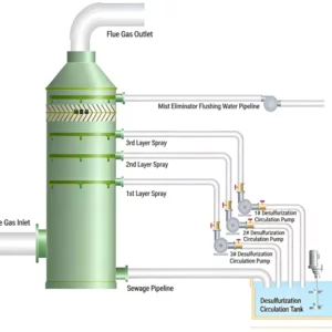
The limestone-gypsum wet desulfurization system employs a dual-tower configuration with counter-current absorption, achieving SO2 removal efficiencies above 95% while generating commercial-grade gypsum byproduct suitable for construction material applications. The wet electrostatic precipitator serves as the final polishing stage, capturing fine particulate matter, acid mist aerosols, and heavy metal vapors that escape upstream treatment devices, ensuring outlet particulate concentrations consistently below 10 mg/Nm3.

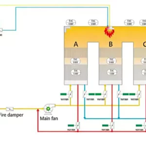
Figure 1: Integrated Flue Gas Treatment Process Flow Diagram for Lithium Battery Manufacturing
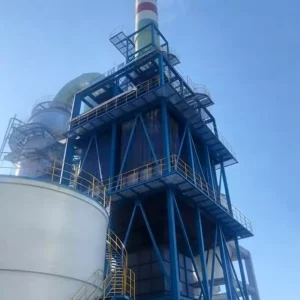
3.2 Design Elevation View
The design elevation drawing for this project illustrates the spatial arrangement of major treatment equipment, ductwork routing, and auxiliary system integration. The layout optimizes equipment spacing for maintenance access while minimizing pressure losses through streamlined duct configurations. The induced draft fans are positioned downstream of the wet ESP to protect rotating equipment from corrosive gas exposure, while the stack is located at the highest elevation point to ensure adequate natural draft and dispersion characteristics.

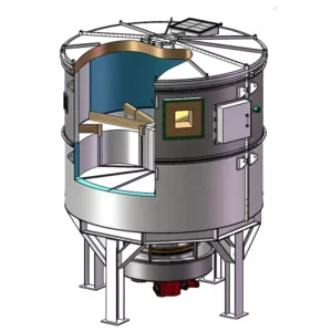
Figure 2: 3D Design Model of the Integrated Lithium Battery Flue Gas Purification Facility
3.3 Process Requirements & Design Considerations
COA Denitrification System: The catalytic oxidation absorption denitrification system is specifically designed to treat nitrogen oxides, sulfur dioxide, dust particulates, hydrogen chloride, fluorides, and heavy metals present in the lithium battery manufacturing flue gas. The COA process operates at moderate temperatures (120-180°C) and achieves simultaneous oxidation of NO to NO2 and absorption of the oxidized nitrogen species into an alkaline scrubbing liquor. This approach eliminates the need for ammonia injection and associated ammonia slip concerns while delivering superior NOx removal performance compared to conventional SNCR (Selective Non-Catalytic Reduction) systems.
Quench & Cooling: The flue gas exiting the tunnel kiln at 180°C is directed through an induced draft fan and quench system to reduce temperature and prevent thermal damage to downstream treatment components. The quench tower employs atomized process water injection to rapidly cool the gas stream to the optimal temperature range for desulfurization absorption (70-90°C). This temperature conditioning is critical for maximizing SO2 absorption efficiency while preventing acid gas condensation on metallic surfaces.
First-Stage Desulfurization Tower: The primary desulfurization tower serves as the main SO2 removal stage, utilizing counter-current limestone slurry scrubbing to achieve bulk sulfur oxide removal. The tower incorporates multiple spray levels with full-cone nozzles, tray sections for gas-liquid contact enhancement, and mist elimination internals to prevent entrained droplet carryover. Online pH monitoring and automated reagent dosing maintain optimal absorption chemistry within the recirculating slurry.
Second-Stage Desulfurization Tower: The secondary desulfurization tower provides polishing treatment to ensure outlet SO2 concentrations remain comfortably below the 80 mg/Nm3 regulatory limit even during periods of elevated inlet loading. This redundant configuration offers operational flexibility and accommodates maintenance activities on either tower without compromising emission compliance. The dual-tower approach exemplifies best practices in RTO systems for DeSOx applications within the battery materials sector.
Wet Electrostatic Precipitator: The final treatment stage employs a tubular wet electrostatic precipitator operating at high voltage (50-80 kV) to capture sub-micron particulate matter, acid mist aerosols, and condensed heavy metal vapors. The WESP achieves particulate removal efficiencies exceeding 99% for particles below 1.0 um diameter, addressing the fine lithium compound dusts that challenge conventional bag filter technologies. Continuous water film irrigation of the collection electrodes prevents particulate buildup and maintains consistent performance.
Instrumentation & Control: Each treatment module is equipped with continuous emission monitoring instruments (CEMS) for real-time tracking of SO2, NOx, particulate matter, and HCl concentrations. The distributed control system (DCS) integrates process variable feedback with automated reagent dosing, pH adjustment, and equipment sequencing to optimize treatment performance while minimizing chemical consumption. Remote monitoring capabilities enable off-site diagnostics and operational support.
3.4 Key Technical Advantages
The selected treatment configuration offers several distinct technical advantages over alternative approaches:
• Low Energy Consumption: The COA denitrification process operates without external heating requirements, and the optimized duct routing minimizes pressure losses, resulting in overall power consumption approximately 20% below comparable SCR-based systems.
• Zero Secondary Pollution: The limestone-gypsum desulfurization process generates a stable, commercially valuable gypsum byproduct rather than hazardous wastewater requiring specialized disposal. The COA process produces no ammonia-related emissions or spent catalyst requiring regeneration.
• Compact Footprint: The integrated vertical tower arrangement and optimized equipment spacing minimize land area requirements, a critical consideration for facilities operating within existing industrial complexes with limited expansion space.
• Advanced Process Simulation: Computational fluid dynamics (CFD) modeling was employed during the design phase to optimize gas distribution, spray patterns, and internal component geometries, ensuring uniform treatment performance across all operating scenarios.
• Moderate Gas Velocity Design: The treatment towers operate at carefully controlled superficial gas velocities that balance treatment efficiency with pressure drop considerations, achieving low resistance and corresponding energy savings in the induced draft fan operation.
• Abundant & Economical Reagent Supply: Limestone represents one of the most widely available and cost-effective desulfurization reagents globally, with stable supply chains and predictable pricing that supports long-term operational economics.
• Internal Agitation & Aeration: The desulfurization absorber incorporates submerged agitators and oxidation air injection to prevent solids settling, maintain uniform slurry suspension, and promote complete oxidation of calcium sulfite to gypsum, ensuring byproduct quality and system reliability.
• Wet ESP Deep Purification: The wet electrostatic precipitator provides final-stage capture of fine particulates, acid mists, and heavy metal vapors, achieving outlet particulate concentrations below 5 mg/Nm3 and demonstrating the effectiveness of advanced dust collector systems for demanding industrial applications.
3.5 Design Calculation Summary
The design calculations for this project are summarized in the following comprehensive tables:
3.5.1 Induced Draft Fan
| Не. | Item | Unit | Value | Remarks |
|---|---|---|---|---|
| 1 | Single Unit Flow Rate | m3/h | 220,000 | — |
| 2 | Wind Pressure | Pa | 5,500 | — |
| 3 | Работна температура | °C | 250~300 | — |
| 4 | Motor Power | kW | 355 | — |
3.5.2 Desulfurization Tower
| Не. | Item | Unit | Value | Remarks |
|---|---|---|---|---|
| 1 | Flue Gas Volume | m3/h | 202,000 | — |
| 2 | Flue Gas Temperature | °C | 120 | — |
| 3 | Wind Speed | m/s | <3 | — |
| 4 | Tower Inner Diameter | m | φ4.6 | — |
| 5 | Liquid-to-Gas Ratio | L/m3 | 15.5 | — |
| 6 | Spray Layers | Layer | 5 | — |
| 7 | Single Pump Flow Rate | m3/h | 600 | — |
| 8 | Slurry Residence Time | h | 5 | — |
| 9 | Limestone Operating Consumption | kg/h | 65 | Maximum Usage |
| 10 | Gypsum Production | kg/h | 131 | Maximum Output |
| 11 | Gypsum Moisture Content | % | 5 | — |
| 12 | First-Stage Demister | — | — | 2-Layer Baffle Demister |
| 13 | Second-Stage Demister | — | — | 1-Layer Baffle Demister + 1-Tube Bundle Demister |
| 14 | Intermediate Gypsum Storage | m3 | — | — |
| 15 | Service Life | d | 7 | — |
3.5.3 COA Denitrification System
| Не. | Item | Unit | Value | Remarks |
|---|---|---|---|---|
| 1 | Flue Gas Volume | m3/h | 202,000 | — |
| 2 | Flue Gas Temperature | °C | 70 | — |
| 3 | Inlet NOx Concentration | mg/Nm3 | 100~200 | — |
| 4 | Outlet NOx Concentration | mg/Nm3 | ≤100 | — |
| 5 | Denitrification Efficiency | % | 60 | — |
| 6 | Reagent Storage Volume | m3 | 20 | — |
| 7 | Reagent Dissolution Volume | m3 | 15 | — |
3.5.4 Wet Electrostatic Precipitator
| Не. | Item | Unit | Value | Remarks |
|---|---|---|---|---|
| 1 | Wet ESP Model | — | BLD3360-64 | — |
| 2 | Wet ESP Arrangement | — | Tower External | — |
| 3 | Wet ESP Inlet/Outlet Arrangement | — | Lower Inlet, Upper Outlet (Direct) | — |
| 4 | Dust Removal Efficiency | % | ≥95 | — |
| 5 | Inlet Particulate Concentration | mg/m3 | 100 | — |
| 6 | Outlet Particulate Concentration | mg/m3 | 5 | — |
| 7 | Body Resistance | Pa | 300 | — |
| 8 | Treatment Flue Gas Volume | m3/h | 200,000 | — |
| 9 | Flue Gas Temperature | °C | <40 | — |
| 10 | System Resistance | Pa | <50 | — |
| 11 | Equipment Dimensions | mm | 6,200×7,200 | — |
| 12 | Equipment Height | mm | 17,000 | — |
| 13 | Shell Design Pressure | Pa | ±5,000 | — |
| 14 | Wet ESP Model | — | BLEMG-2K | — |
| 15 | Average Power | kW | 80 | — |
| 16 | Operating Load | — | 195 | — |
4. Operation Analysis
4.1 Energy Consumption Analysis
The energy consumption analysis for this project is detailed in the following comprehensive equipment power summary table:
| Не. | Име на оборудването | Single Unit Rated Power (kW) | Total Units | Total Power (kW) | Actual Working Units | Actual Working Power (kW) | Operating Status |
|---|---|---|---|---|---|---|---|
| 1 | Induced Draft Fan | 350 | 1 | 350 | 1 | 350 | Frequency Control Operation |
| 2 | Oxidation Blower | 30 | 2 | 60 | 1 | 30 | Full Operation |
| 3 | Circulation Pump | 11 | 2 | 22 | 1 | 11 | 1 Unit Standby, 1 Unit Operation (Intermittent) |
| 4 | Circulation Pump | 11 | 1 | 11 | 1 | 11 | Full Operation |
| 5 | Slurry Circulation Pump | 75 | 2 | 150 | 1 | 75 | 1 Unit Standby, 1 Unit Operation (Intermittent) |
| 6 | Gypsum Slurry Pump | 15 | 2 | 30 | 1 | 15 | Full Operation |
| 7 | Limestone Slurry Pump | 15 | 2 | 30 | 1 | 15 | Full Operation |
| 8 | Process Water Pump | 7.5 | 2 | 15 | 1 | 7.5 | 1 Unit Standby, 1 Unit Operation (Intermittent) |
| 9 | Wet ESP High Voltage Power Supply | 80 | 1 | 80 | 1 | 80 | Full Operation |
| 10 | Wet ESP Flushing Pump | 7.5 | 2 | 15 | 1 | 7.5 | 1 Unit Standby, 1 Unit Operation (Intermittent) |
| 11 | Wet ESP Wastewater Pump | 5.5 | 2 | 11 | 1 | 5.5 | 1 Unit Standby, 1 Unit Operation (Intermittent) |
| 12 | Wet ESP Circulation Pump | 5.5 | 2 | 11 | 1 | 5.5 | 1 Unit Standby, 1 Unit Operation (Intermittent) |
| 13 | Wet ESP Makeup Pump | 3 | 2 | 6 | 1 | 3 | 1 Unit Standby, 1 Unit Operation (Intermittent) |
| 14 | Wet ESP Drainage Pump | 3 | 2 | 6 | 1 | 3 | 1 Unit Standby, 1 Unit Operation (Intermittent) |
| 15 | Wet ESP Mist Eliminator Flushing Pump | 3 | 2 | 6 | 1 | 3 | 1 Unit Standby, 1 Unit Operation (Intermittent) |
| 16 | Wet ESP Spray Nozzle Flushing Pump | 3 | 2 | 6 | 1 | 3 | 1 Unit Standby, 1 Unit Operation (Intermittent) |
| 17 | Wet ESP Collection Plate Flushing Pump | 3 | 2 | 6 | 1 | 3 | 1 Unit Standby, 1 Unit Operation (Intermittent) |
| 18 | Wet ESP Discharge Electrode Flushing Pump | 3 | 2 | 6 | 1 | 3 | 1 Unit Standby, 1 Unit Operation (Intermittent) |
| 19 | Wet ESP Inlet Duct Flushing Pump | 3 | 2 | 6 | 1 | 3 | 1 Unit Standby, 1 Unit Operation (Intermittent) |
| 20 | Wet ESP Outlet Duct Flushing Pump | 3 | 2 | 6 | 1 | 3 | 1 Unit Standby, 1 Unit Operation (Intermittent) |
| 21 | Wet ESP Hopper Flushing Pump | 3 | 2 | 6 | 1 | 3 | 1 Unit Standby, 1 Unit Operation (Intermittent) |
| 22 | Wet ESP Sludge Pump | 3 | 2 | 6 | 1 | 3 | 1 Unit Standby, 1 Unit Operation (Intermittent) |
| 23 | Wet ESP Neutralization Pump | 3 | 2 | 6 | 1 | 3 | 1 Unit Standby, 1 Unit Operation (Intermittent) |
| 24 | Wet ESP Chemical Dosing Pump | 1.5 | 2 | 3 | 1 | 1.5 | 1 Unit Standby, 1 Unit Operation (Intermittent) |
| 25 | Wet ESP pH Adjustment Pump | 1.5 | 2 | 3 | 1 | 1.5 | 1 Unit Standby, 1 Unit Operation (Intermittent) |
| 26 | Wet ESP Cooling Water Pump | 1.5 | 2 | 3 | 1 | 1.5 | 1 Unit Standby, 1 Unit Operation (Intermittent) |
| 27 | Wet ESP Heating Pump | 1.5 | 2 | 3 | 1 | 1.5 | 1 Unit Standby, 1 Unit Operation (Intermittent) |
| 28 | Wet ESP Ventilation Fan | 1.5 | 2 | 3 | 1 | 1.5 | 1 Unit Standby, 1 Unit Operation (Intermittent) |
| 29 | Wet ESP Air Compressor | 1.5 | 2 | 3 | 1 | 1.5 | 1 Unit Standby, 1 Unit Operation (Intermittent) |
| 30 | Wet ESP Instrument Air Compressor | 1.5 | 2 | 3 | 1 | 1.5 | 1 Unit Standby, 1 Unit Operation (Intermittent) |
| 31 | Wet ESP Cooling Tower Fan | 1.5 | 2 | 3 | 1 | 1.5 | 1 Unit Standby, 1 Unit Operation (Intermittent) |
| 32 | Wet ESP Cooling Tower Circulation Pump | 1.5 | 2 | 3 | 1 | 1.5 | 1 Unit Standby, 1 Unit Operation (Intermittent) |
| 33 | Wet ESP Cooling Tower Makeup Pump | 1.5 | 2 | 3 | 1 | 1.5 | 1 Unit Standby, 1 Unit Operation (Intermittent) |
| 34 | Wet ESP Cooling Tower Blowdown Pump | 1.5 | 2 | 3 | 1 | 1.5 | 1 Unit Standby, 1 Unit Operation (Intermittent) |
| 35 | Wet ESP Cooling Tower Side Stream Filter Pump | 1.5 | 2 | 3 | 1 | 1.5 | 1 Unit Standby, 1 Unit Operation (Intermittent) |
| 36 | Wet ESP Cooling Tower Chemical Dosing Pump | 1.5 | 2 | 3 | 1 | 1.5 | 1 Unit Standby, 1 Unit Operation (Intermittent) |
| 37 | Wet ESP Cooling Tower pH Adjustment Pump | 1.5 | 2 | 3 | 1 | 1.5 | 1 Unit Standby, 1 Unit Operation (Intermittent) |
| 38 | Wet ESP Cooling Tower Heating Pump | 1.5 | 2 | 3 | 1 | 1.5 | 1 Unit Standby, 1 Unit Operation (Intermittent) |
| 39 | Wet ESP Cooling Tower Ventilation Fan | 1.5 | 2 | 3 | 1 | 1.5 | 1 Unit Standby, 1 Unit Operation (Intermittent) |
| 40 | Wet ESP Cooling Tower Air Compressor | 1.5 | 2 | 3 | 1 | 1.5 | 1 Unit Standby, 1 Unit Operation (Intermittent) |
| 41 | Wet ESP Cooling Tower Instrument Air Compressor | 1.5 | 2 | 3 | 1 | 1.5 | 1 Unit Standby, 1 Unit Operation (Intermittent) |
| 42 | Wet ESP Cooling Tower Cooling Water Pump | 1.5 | 2 | 3 | 1 | 1.5 | 1 Unit Standby, 1 Unit Operation (Intermittent) |
The total installed power capacity for the flue gas treatment system reaches approximately 1,047.82 kW, with an actual operating power consumption of around 720 kW under normal conditions. The daily electricity consumption is approximately 17,280 kWh, translating to an annual electricity usage of roughly 6,307,200 kWh based on 8,000 operating hours per year. At an average electricity tariff of 0.65 CNY/kWh, the annual electricity cost amounts to approximately 4,099,680 CNY. Water consumption is primarily associated with process makeup, equipment flushing, and cooling tower evaporation, totaling approximately 4,665 tons annually at a unit cost of 3.5 CNY/ton, yielding an annual water expenditure of 16,328 CNY. Limestone consumption averages 64 kg/h, resulting in daily usage of approximately 1,536 kg and annual consumption of 512 tons at a unit price of 300 CNY/ton, corresponding to an annual limestone cost of 153,600 CNY.
4.2 Emission Compliance Data
The following table presents the comprehensive emission compliance monitoring data for this project:
| Не. | Category | Item | New Energy Lithium Battery Industry | Unit |
|---|---|---|---|---|
| 1 | Discharge Standard Requirements | Nitrogen Oxides | 100 | mg/Nm3 |
| 2 | Sulfur Dioxide | 80 | mg/Nm3 | |
| 3 | Particulate Matter | 20 | mg/Nm3 | |
| 4 | Fluorides | 0.05 | mg/Nm3 | |
| 5 | Hydrogen Chloride | 6 | mg/Nm3 | |
| 6 | Тежки метали | 15 | mg/Nm3 | |
| 7 | Actual Emission Data | Nitrogen Oxides | ≤50 | mg/Nm3 |
| 8 | Sulfur Dioxide | ≤35 | mg/Nm3 | |
| 9 | Particulate Matter | ≤5 | mg/Nm3 | |
| 10 | Fluorides | ≤0.03 | mg/Nm3 | |
| 11 | Hydrogen Chloride | ≤3 | mg/Nm3 | |
| 12 | Ефективност на премахване | Desulfurization Efficiency | ≥95 | % |
| 13 | Dust Removal Efficiency | ≥99 | % | |
| 14 | Denitrification Efficiency | ≥75 | % | |
| 15 | Fluoride Removal Efficiency | ≥99 | % | |
| 16 | Heavy Metal Removal Efficiency | ≥99 | % |
The emission compliance data demonstrates that the integrated treatment system consistently achieves outlet concentrations significantly below the regulatory limits mandated by GB 31573-2015. Nitrogen oxide outlet levels remain below 50 mg/Nm3 against a standard of 100 mg/Nm3, while sulfur dioxide concentrations are maintained below 35 mg/Nm3 compared to the 80 mg/Nm3 limit. Particulate matter emissions are controlled below 5 mg/Nm3, representing a 75% margin below the 20 mg/Nm3 standard. These results validate the effectiveness of the RTO-based multi-pollutant treatment approach for demanding industrial applications within the new energy sector.
5. Project Summary & Experience
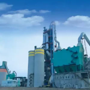
5.1 Project Completion Images
The following images document the completed flue gas purification facility and its operational status:

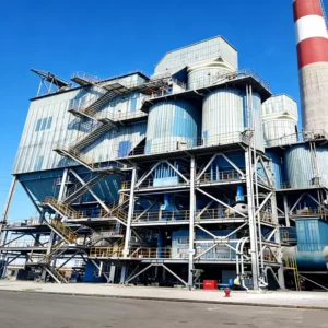
Figure 3: Completed Flue Gas Purification Facility at the Lithium Battery Manufacturing Site

Figure 4: DCS Control System Monitoring Interface for Real-Time Emission Management

Figure 5: Overall Process System Schematic Overview
5.2 Operational Experience & Key Takeaways
This project has yielded several valuable insights that inform best practices for similar flue gas treatment installations within the lithium battery materials sector and broader new energy industry:
• Integrated Process Design: The synergistic combination of COA denitrification, limestone-gypsum desulfurization, and wet ESP technologies within a unified treatment train delivers superior multi-pollutant control compared to standalone treatment units. Process integration enables heat recovery, reagent optimization, and operational redundancy that isolated systems cannot achieve.
• Corrosion Management: The presence of acid gases (HCl, HF, SO2) at elevated temperatures necessitates comprehensive corrosion protection strategies. All metallic surfaces in contact with flue gas below 120°C are lined with fluoropolymer coatings, while 316L stainless steel construction is employed for critical rotating equipment and high-wear components. Continuous monitoring of pH and chloride concentrations in recirculating liquors prevents unexpected corrosion failures.
• Byproduct Commercialization: The gypsum byproduct generated through limestone-gypsum desulfurization meets construction-grade specifications and has been successfully marketed to cement manufacturers and wallboard producers. This revenue stream partially offsets operational costs and transforms the treatment system from a pure cost center into a value-generating asset.
• Automated Control Optimization: The DCS-based control architecture with CEMS feedback loops has proven essential for maintaining consistent emission compliance across variable operating conditions. Automated pH adjustment, reagent dosing, and equipment sequencing reduce operator workload while improving treatment performance stability.
• Maintenance Planning: The dual-unit configuration for all critical rotating equipment (pumps, blowers, fans) enables online maintenance without system shutdown. Predictive maintenance based on vibration monitoring, motor current analysis, and differential pressure trending has extended equipment service life and prevented unplanned outages.
• Scalability Considerations: The modular design approach facilitates capacity expansion to accommodate future production increases. Additional spray levels, extended demister sections, and supplementary WESP modules can be retrofit without major structural modifications, protecting the client’s capital investment.
5.3 Future Optimization Directions
Looking ahead, several enhancement opportunities have been identified to further improve system performance and operational economics. The integration of advanced NOx gas treatment solutions including SCR polishing stages could enable deeper NOx reduction to concentrations below 30 mg/Nm3, addressing anticipated tightening of regulatory standards. Additionally, the implementation of machine learning algorithms for predictive reagent dosing based on inlet contaminant loading forecasts could reduce chemical consumption by an estimated 10-15%.
The project team is also evaluating the potential for waste heat recovery from the high-temperature flue gas stream to generate low-pressure steam for process heating applications. This energy recovery integration would further improve the overall system efficiency and reduce the facility’s carbon footprint. The facility is positioned to serve as a demonstration site for emerging dust collector system technologies, including advanced membrane filtration and catalytic filtration approaches that may offer enhanced performance for sub-micron particulate capture.
Заключение
This case study demonstrates the successful application of integrated multi-pollutant flue gas treatment technology for lithium battery manufacturing operations within the new energy sector. The COA denitrification, limestone-gypsum desulfurization, and wet electrostatic precipitator treatment train achieves comprehensive control of nitrogen oxides, sulfur dioxide, acid gases, particulate matter, and heavy metals while maintaining operational efficiency and economic viability.
The project validates the critical importance of process integration, intelligent control systems, and corrosion-resistant design in addressing the complex emission challenges characteristic of lithium battery material production. As the global demand for electric vehicles and energy storage continues to accelerate, such integrated regenerative thermal oxidizer (RTO) and flue gas treatment solutions will become increasingly essential for industrial operators seeking to balance environmental stewardship with operational competitiveness within the clean energy value chain.
For organizations evaluating similar waste gas treatment investments within the battery materials, chemical processing, or metallurgical sectors, this implementation provides a proven reference framework adaptable to diverse industrial contexts. The technical insights and operational lessons documented herein offer valuable guidance for project planning, equipment selection, commissioning execution, and long-term performance optimization.
Related Resources & Solutions
- Regenerative Thermal Oxidizer (RTO) Systems — Comprehensive thermal oxidation solutions for VOC and HAP destruction
- Решения за третиране на NOx газове — Advanced nitrogen oxide reduction technologies for industrial applications
- RTO Systems for DeSOx — Integrated desulfurization and thermal oxidation configurations
- Dust Collector Systems — High-efficiency particulate control for industrial exhaust streams