
Design the RCO layout around the work that must happen later
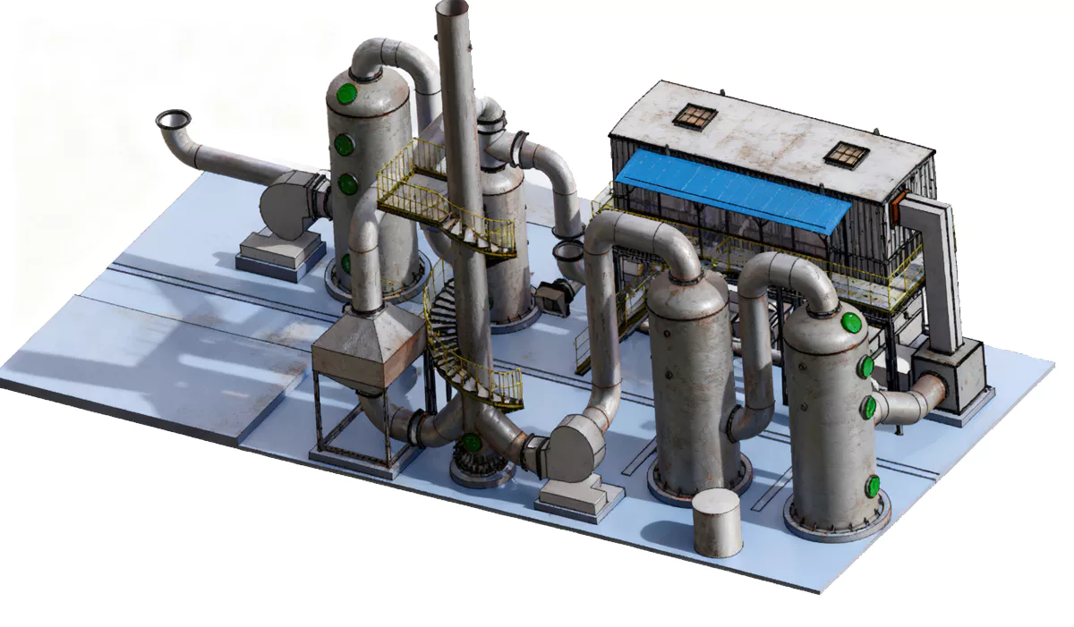
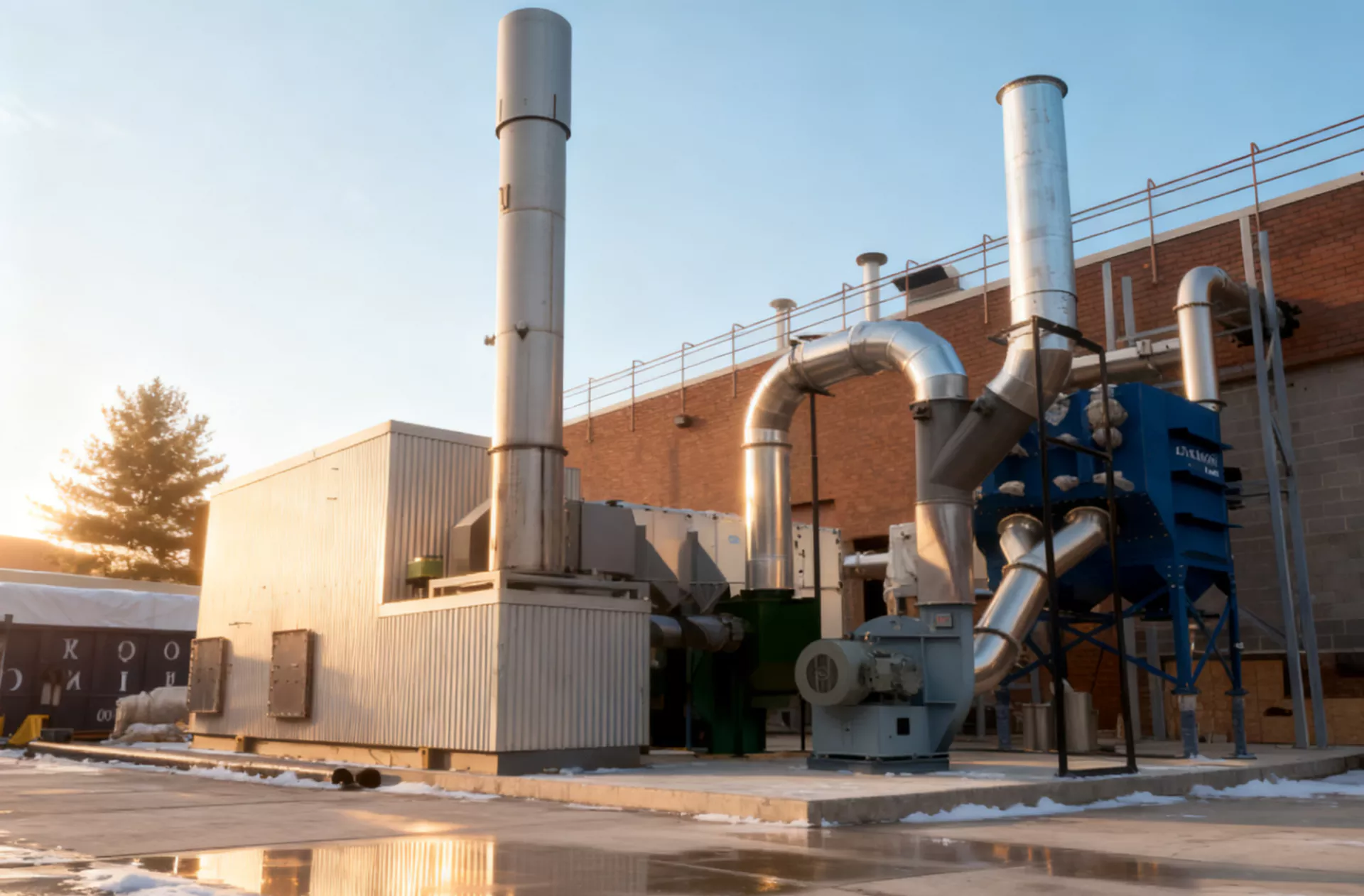
A workable RCO layout includes more than the vessel footprint. Access for inspection, module removal, lifting, sampling, isolation, instrument service, and duct maintenance should be checked against the actual site before foundations and connections are frozen.
An RCO layout should be judged by whether the installed equipment can be operated and maintained safely, not merely whether the vessel fits inside the available boundary. The footprint drawing may not show the space needed to open an access door, remove a catalyst module, reach an instrument, or lift a heavy component. These service movements should be considered before foundations and duct routes become difficult to change.
Start with a site survey that records floor area, overhead clearance, structural obstructions, nearby services, access routes, and the likely installation sequence. Confirm the dimensions against current drawings rather than relying only on an old general arrangement. If the survey reveals unknown structural capacity or lifting limitations, assign a qualified review before the layout is treated as approved.
Use the documented RCO installation-interface review as a reminder to list each connection and responsibility, then adapt it to the new site. The package boundary should identify who supplies inlet and outlet ductwork, supports, insulation, platforms, wiring, utilities, controls integration, and access for commissioning. Ambiguous scope often appears first as a layout problem on site.
Catalyst access should be planned from the actual module design. Confirm removal direction, lifting points, handling orientation, module dimensions, temporary staging space, and the path to the maintenance area. A drawing that shows a removable element is not enough if a handrail, cable tray, pipe, or wall blocks the required movement. Review the real removal envelope with the people who will perform the task. The catalyst handling and storage guidance can help identify module-specific movement and staging questions.
Service envelope
Reserve space for doors, tools, module movement, and the people who must perform inspections.
Safe access
Review platforms, lifting routes, isolation points, and sampling access with site safety and maintenance staff.
Interface ownership
Document which party provides ducts, supports, wiring, utilities, and commissioning access.
Consider the need to isolate, cool, and verify the equipment before intrusive work. The layout should allow access to the required isolation devices, vents, drains, gas-testing points, and other provisions specified by the approved procedure. Exact requirements depend on the system and site hazards. Do not improvise an isolation method after installation because the preferred valve or access point was omitted from the drawing.
Sampling access is another layout item that is easy to postpone. The required sampling location should be selected by qualified personnel according to the applicable method and duct arrangement. Ensure there is suitable access, safe working space, and room for the sampling equipment. A technically correct port that cannot be reached safely may create a recurring testing and compliance problem.
Instrument maintenance needs space too. Pressure transmitters, temperature sensors, flow devices, and valve feedback components should be reachable for inspection and calibration as intended by the design. Avoid placing access panels behind permanent piping or positioning a sensor where replacement requires dismantling unrelated equipment. Include cable routing and instrument removal in the layout review rather than checking only the process pipework.
Duct geometry should be checked with both flow and maintenance in mind. Elbows, transitions, supports, expansion provisions, dampers, and access doors can influence pressure resistance and the ability to inspect deposits. The design team should use the approved engineering basis for duct sizing and support. Maintenance access should not be added by cutting an unreviewed opening into a duct that carries hot or potentially hazardous exhaust.
Fan placement affects noise, vibration, lifting access, and the route of electrical and control services. Confirm the maintenance clearance required by the fan and drive supplier, including space to remove a motor or other serviceable part. The arrangement should also permit safe inspection of the inlet and discharge connections. A compact layout can become expensive if every repair requires moving unrelated equipment.
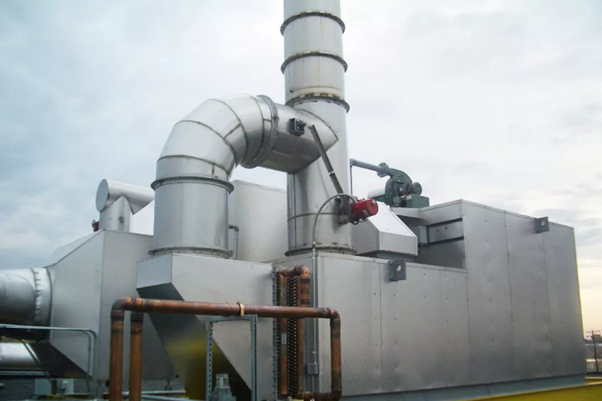
Review the real removal envelope for catalyst modules and service parts, including overhead clearance and the route to a safe staging area.
Thermal expansion and insulation deserve attention where hot sections connect to ducts or supports. The arrangement should follow the approved mechanical design and material requirements. Check that insulation does not hide required inspection points or prevent access to valves and instruments. Do not treat the insulation boundary as a cosmetic decision; it can affect worker access and the ability to identify leakage or deterioration.
If the equipment is installed outdoors, consider the site’s environmental conditions and maintenance practices. Rain exposure, drainage, wind, corrosion, access during adverse weather, and protection of instruments may be relevant. The exact provisions should be selected for the actual site, not copied from a different project. Keep the service plan realistic for the conditions in which technicians will work.
Foundation and lifting plans should be coordinated with delivery dimensions and the installation sequence. Confirm the route from unloading to final position, door and crane clearances, floor loading, temporary supports, and any restrictions from adjacent operations. If a major component cannot be moved into the space after walls or pipe racks are installed, the design needs to resolve that before construction begins.
Layout should preserve access to safety and control devices. Operators and maintenance staff must be able to see the relevant indicators and reach approved controls without crossing unsafe areas or removing guards. The exact location depends on the site hazard assessment and operating philosophy. A convenient HMI location is not a substitute for a safe physical route to equipment that requires inspection or isolation.
Resolve maintainability before the layout is frozen
Before freezing the drawing, hold a maintainability review with operations, maintenance, engineering, safety, and the equipment supplier. Walk through common tasks: inspect an instrument, replace a filter, open an access door, remove a module, collect a sample, and restore the system to service. If any task relies on an assumed tool or unplanned dismantling, record the issue and revise the layout or procedure.
Use a layout register to capture decisions and outstanding items. Each item should state the drawing reference, responsible party, verification method, and status. Examples include an unconfirmed lifting route, missing sampling access, uncertain foundation capacity, or a valve that cannot be reached. This register is particularly useful when mechanical, electrical, civil, and process scopes are delivered by different contractors.
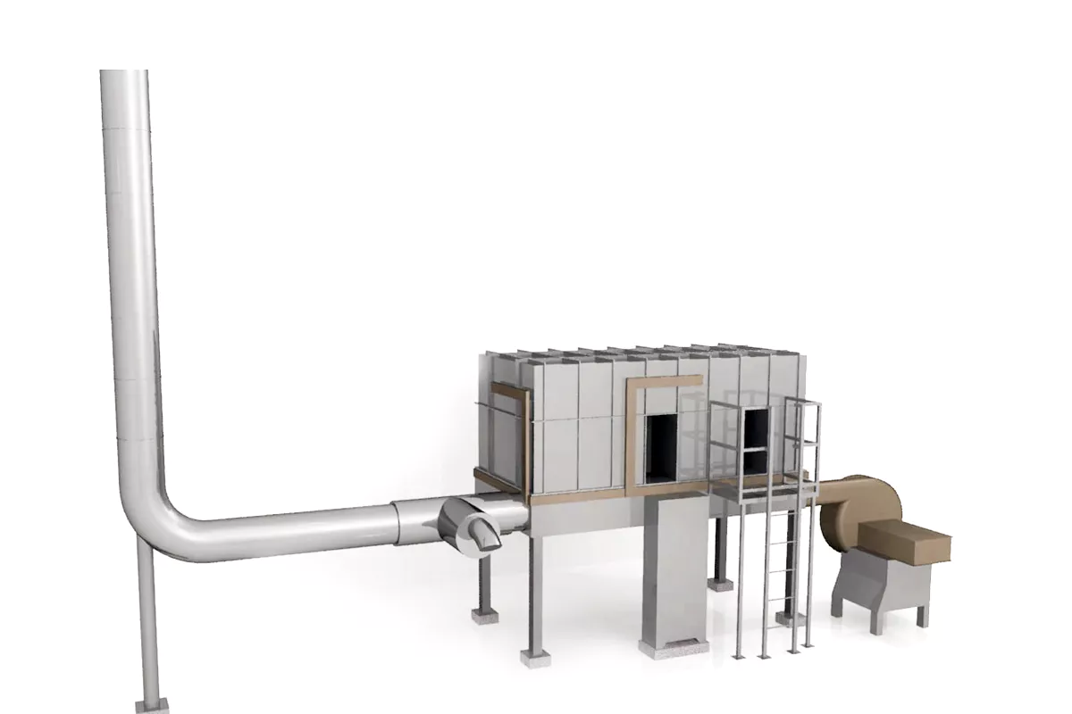
Access and isolation must follow the site-specific hazard review and approved work procedures. Do not solve an access problem by improvising an unsafe bypass or opening.
Commissioning access should be planned as part of the construction layout. Technicians may need to connect test instruments, inspect signals, verify flow direction, confirm device movement, and perform the approved acceptance tests. Leave space for temporary equipment and safe access around the relevant points. If these needs are ignored, commissioning can be delayed even when the major equipment has arrived on time.
As-built drawings should capture the final location of equipment, valves, instruments, platforms, ducts, and access provisions. Mark approved field changes and update the maintenance documentation before handover. An old drawing that looks close to the installed arrangement can be misleading when a technician is preparing isolation or lifting. The record should represent the actual system rather than the original design intent.
| Layout item | Field check | Potential consequence if missed |
|---|---|---|
| Module access | Door swing, lifting points, extraction path, staging | A serviceable part may be impossible to remove |
| Sampling point | Approved location, working platform, equipment clearance | Testing becomes unsafe or impractical |
| Instruments | Reach, calibration access, cable and tubing routes | Routine checks require unnecessary dismantling |
| Fan and ducts | Service clearance, support, expansion, access doors | Repair time and pressure issues become harder to manage |
| Isolation provisions | Reachable devices and required verification points | Maintenance sequence may not match the approved procedure |
Practical review workflow
Survey the actual site and confirm current drawings and constraints.
Review installation and maintenance movements, not just the vessel footprint.
Verify module extraction, sampling, instrument, and fan service access.
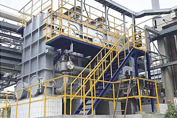
Resolve lifting, structural, duct, utility, and package-boundary responsibilities.
Walk through commissioning tasks and record unresolved access issues.
Confirm the as-built installation matches the approved service and safety plan.
Maintenance planning should confirm where removed components will be inspected, cleaned if permitted, stored, or prepared for replacement. Keep the route clear and identify any temporary staging restrictions. Do not assume a module can be left in an operating aisle or exposed to contamination while waiting for a supplier decision. Storage and handling should follow the instructions for the actual component.
Layout and maintainability also affect lifecycle cost. Difficult access can increase labor, extend shutdown duration, or require temporary lifting equipment. Those consequences should be considered alongside initial construction cost, without inventing a precise saving. A review that identifies a removable handrail or service platform before fabrication may prevent repeated workarounds over the life of the installation. Cross-check the RCO maintenance planning checklist to ensure routine service tasks are reflected in the final layout.
Before handover, verify that the access provisions shown on drawings exist in the field and can support the intended task. Record unresolved restrictions and the approved control for each one. The installation should not be considered maintainable simply because a platform or access door appears on a drawing; it must work with the actual surrounding equipment and safe-work procedure.
A good RCO layout makes routine work foreseeable. It gives people safe access to the equipment, provides space for removal and testing, clarifies package boundaries, and preserves an accurate as-built record. When maintainability is reviewed early, the site is less likely to discover after startup that a service task is physically impossible without a costly modification.
Những câu hỏi thường gặp
Is the equipment footprint enough for layout approval?
No. Doors, lifting, module removal, sampling, instrument service, and safe access also require space.
Who should join a maintainability review?
Include operations, maintenance, engineering, safety, and the equipment supplier so the real tasks and restrictions are represented.
Can sampling ports be added after installation?
Possibly, but location and modification must be reviewed against the applicable method, duct design, safety, and site approval requirements.
Why keep an as-built layout?
It supports safe isolation, lifting, troubleshooting, maintenance planning, and later modifications based on the actual installed arrangement.
What if a maintenance task cannot be completed safely?
Stop and resolve the issue through the approved engineering and work-planning process rather than improvising access or bypassing a safeguard.
Design the service path before the equipment arrives
Confirm access, lifting, sampling, isolation, and package boundaries in the field. Keep the final drawings aligned with the installed layout and approved work procedures.
 VI
 EN
 ZH
 ES
 AR
 ID
 PT
 FR
 JA
 RU
 DE
 MS
 CS
 BG
 NL
 KO
 RO
 SK
 TH
 ZH_TW
 UK